Team:Calgary/Project/FRED/Reporting
From 2012.igem.org
Emily Hicks (Talk | contribs) |
|||
| Line 48: | Line 48: | ||
<p>With the chemicals finalized we now needed to construct our circuits. | <p>With the chemicals finalized we now needed to construct our circuits. | ||
| - | There is a <i>lacZ</i> gene under the control of the <i>lacI</i> promoter in the registry already registry (<a class="green" href="http://partsregistry.org/Part:BBa_I732901">BBa_I732901</a>). Upon testing this circuit however, it was determined to not be functional. In a simple assay where we added CPRG to cells expressing this part and induced with 200 mM IPTG, we saw no color change, as we would have expected if the LacZ enzyme was being produced and cleaving the CPRG (yellow) into CPR (red). This can be seen below</p> <p></html>[[File:UofC LacZ assay data.jpg| | + | There is a <i>lacZ</i> gene under the control of the <i>lacI</i> promoter in the registry already registry (<a class="green" href="http://partsregistry.org/Part:BBa_I732901">BBa_I732901</a>). Upon testing this circuit however, it was determined to not be functional. In a simple assay where we added CPRG to cells expressing this part and induced with 200 mM IPTG, we saw no color change, as we would have expected if the LacZ enzyme was being produced and cleaving the CPRG (yellow) into CPR (red). This can be seen below</p> <p></html>[[File:UofC LacZ assay data.jpg|250px]][[File:UofC_LacZ2!.jpg|400px]]<html></p>. |
<p> Sequencing of this part showed that it had a frameshift mutation. Original validation of our system was thus done using one of the constitutive <i>lacZ</i> hits from the <a href="https://2012.igem.org/Team:Calgary/Project/FRED/Detecting">transposon screen</a>. After Regionals, a new circuit was constructed and submitted as <a href="http://partsregistry.org/Part:BBa_K902090">BBa_K902090</a>. A similar assay was performed and the results can be seen above as well. On the right is the new circuit, while on the left, the old circuit. The red color indicates that the new pat is indeed functional. This circuit was used in later testing using the LacZ enzyme. The <i>bglX</i> and <i>uidA</i> genes were amplified from the <i>E. coli</i> genome using PCR and biobricked as <a href="http://partsregistry.org/Part:BBa_K902004">BBa_K902004</a> and <a href="http://partsregistry.org/Part:BBa_K902000">BBa_K902000</a> respectively. These genes were then constructed under the <a href="http://partsregistry.org/Part:BBa_R0010"><i>lacI</i> promoter</a> to allow for comparison testing.</p> | <p> Sequencing of this part showed that it had a frameshift mutation. Original validation of our system was thus done using one of the constitutive <i>lacZ</i> hits from the <a href="https://2012.igem.org/Team:Calgary/Project/FRED/Detecting">transposon screen</a>. After Regionals, a new circuit was constructed and submitted as <a href="http://partsregistry.org/Part:BBa_K902090">BBa_K902090</a>. A similar assay was performed and the results can be seen above as well. On the right is the new circuit, while on the left, the old circuit. The red color indicates that the new pat is indeed functional. This circuit was used in later testing using the LacZ enzyme. The <i>bglX</i> and <i>uidA</i> genes were amplified from the <i>E. coli</i> genome using PCR and biobricked as <a href="http://partsregistry.org/Part:BBa_K902004">BBa_K902004</a> and <a href="http://partsregistry.org/Part:BBa_K902000">BBa_K902000</a> respectively. These genes were then constructed under the <a href="http://partsregistry.org/Part:BBa_R0010"><i>lacI</i> promoter</a> to allow for comparison testing.</p> | ||
Latest revision as of 03:58, 27 October 2012


Hello! iGEM Calgary's wiki functions best with Javascript enabled, especially for mobile devices. We recommend that you enable Javascript on your device for the best wiki-viewing experience. Thanks!
A Novel Electrochemical Reporting System

For FRED to be able to tell us about the toxins he's sensing we needed a good reporter system that could function in a wide array of environments. Unfortunately the traditional fluorescent or luminescent reporters have significant drawbacks that prevent them from being useful in a tailings environment that is murky and potentially anaerobic. Due to these limitations we decided to improve upon last year's single output electrochemical sensor using the lacZ gene to cleave a substrate into an easily detectable analyte. Our team has developed a novel system that utilizes three separate reporter genes to provide a triple-output electrochemical biosensor and can be used in a wide variety of applications. This system overcomes traditional reporters in that it is fast, accurate, and can function in turbid environments and even in the absence of oxygen!
Why Choose Hydrolases?
To get our bacterial biosensors to report toxic compounds present in the tailings ponds, we needed a quick and reliable system that would function in a variety of aqueous environments. We turned to electrochemistry for this, as the turbidity of the solution doesn't affect the results and nanomolar levels of chemicals can consistently be detected. The idea behind electrochemistry is that the bacteria would either cleave a substrate to produce an oxidizable product (analyte), or transfer electrons directly into an electrode. The three most common methods through which bacteria produce an electrical response are the activities of phosphatases, hydrolases, and metal respiration.
The first system, that of the respiration of metals, involves using an organism that uses metal ions, such as Fe3+, as the terminal electron acceptors in the cellular respiration pathways. While this kind of a system has the potential to be useful in creating bioelectricity, its use as a biosensor is limited. This is because it requires putting one of the essential electron transport genes under an inducible promoter, such that when the promoter is activated, respiration is enabled causing a change in current. Although these bacteria can usually respire more than one type of metal, they bottleneck to a single pathway and output.
The second system relies on phosphatases: enzymes that remove a phosphate group from an electrochemical analyte. When the phosphate group is removed the resultant product could be oxidized or reduced at an electrode to produce a response that would be measured as a change in current. While this method solves the problem of reduced cell viability created in the first system, it also is limited to a single output, as the non-specific phosphatases would act on all substrates in a solution. The effectiveness of the system could be further reduced by background expression of phosphatases in the bacterium, as these enzymes are essential for processes such as signalling and metabolism.
With this in mind we favoured a hydrolase based system, which offers the versatility and sensitivity of electrochemistry, without the pitfalls of disrupting metabolism or the limitations of a single channel output.
How Does it Work?
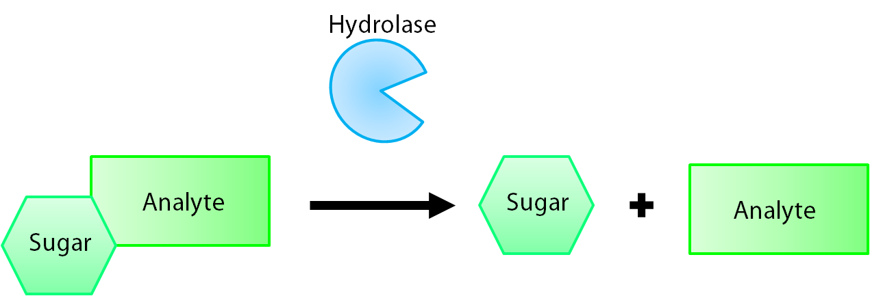
The enzymes encoded by our reporter genes are specific sugar hydrolases. This means that they target one kind of sugar and remove it from whatever compound they are attached to. We have chosen to use the sugars glucose, glucuronide, and galactose for our system. The genes responsible for their respective hydrolases are bglX (BBa_K902004), uidA (BBa_K902000), and lacZ (BBa_I732005). By having our electrochemical analyte conjugated to this sugar, when the hydrolase is expressed the sugar is cleaved from the analyte, allowing for its electrochemical detection. A diagrammatic representation of this system is shown below in Figure 1.
After the analyte is released we need to detect it. Electrochemistry is an excellent approach for this because of its fast and quantitative nature. A voltage is applied between two electrodes compared to a reference electrode and the resulting current is measured. By changing the applied voltage to that of the oxidation voltage of one of our analytes, the increase in current due to its oxidation when compared to an analyte free baseline is proportional to the amount of analyte present in the solution. This process happens so quickly that you can have an output value in a matter of seconds.
We used two different electrochemical techniques in our testing depending on what question the experiment was trying to answer. When we were characterizing the voltages at which our products oxidized we used cyclic voltammetry, which is where you apply a voltage and then slowly increase and decrease it over a designated sweep range. Any bumps in the graph are due to a reaction and can be standardized against baseline measurements. After the oxidation potential has been localized we can speed up our experiments by using potentiostatic runs. In this case, instead of sweeping the voltage we apply to the solution we hold it steady at the voltage that will oxidize our compound the moment it is released into the solution. Both of these techniques require the three electrodes in an electrolyte solution such as phosphate buffered saline and can routinely detect nanomolar concentrations of electrochemical analytes.
Genes, Chemicals, and Circuits
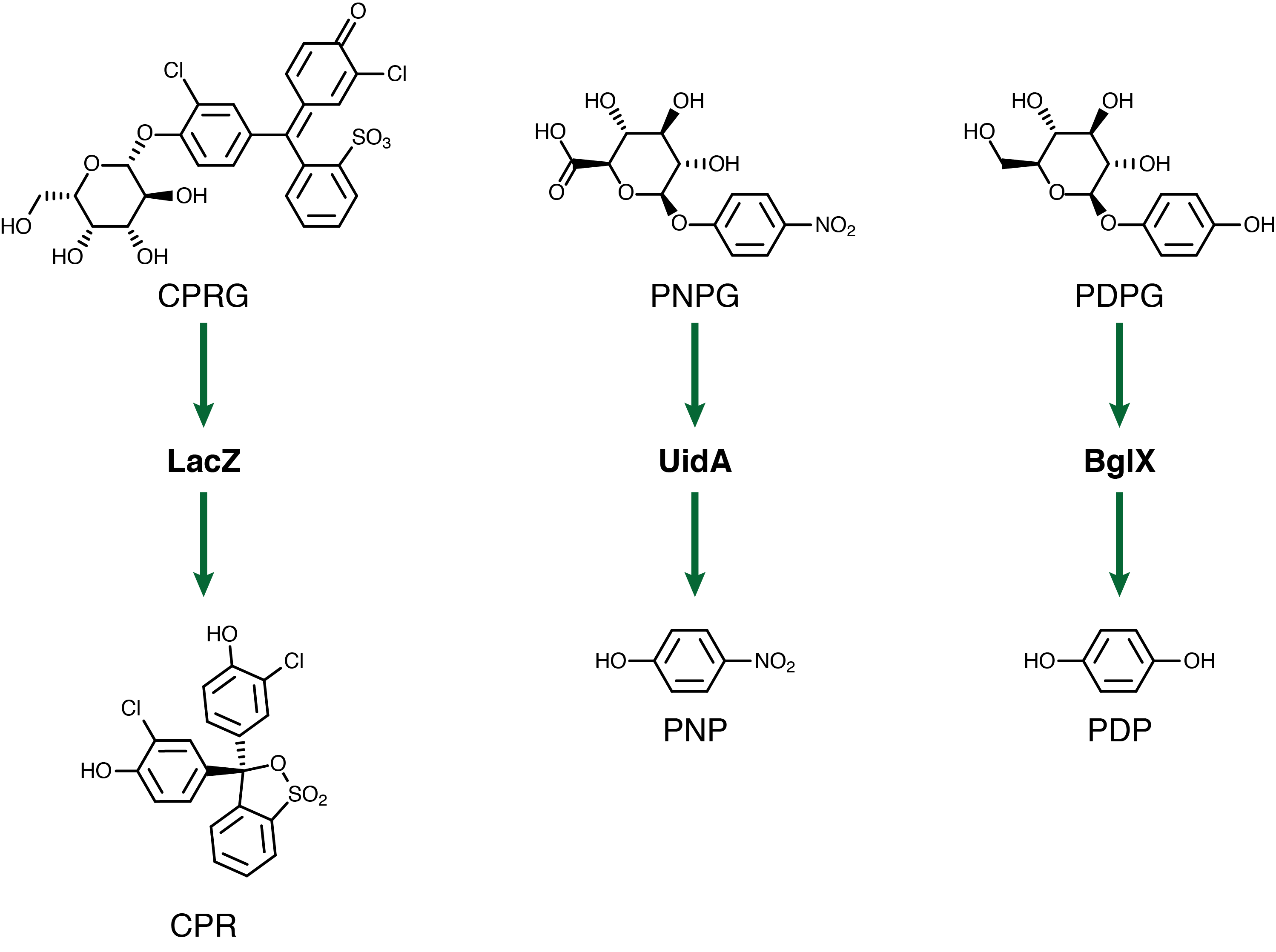
For our system to have a triple output we need three separate genetic circuits with three analytes possessing unique oxidation potentials. If one chemical overlaps with another we could get false-positives of one chemical due to oxidation of another. To this end we have chosen to use chlorophenol red (CPR), para-diphenol (PDP), and para-nitrophenol (PNP). These compounds are conjugated with their sugars to form CPR-β-D-galactopyranoside (CPRG), PDP-β-D-glucopyranoside (PDPG), and PNP-β-D-glucuronide (PNPG). An easy way to tell the analytes from their sugar conjugates is the addition of the letter G to the acronym. These chemicals are summarized below in Figure 2 along with the reporter genes used with each one.
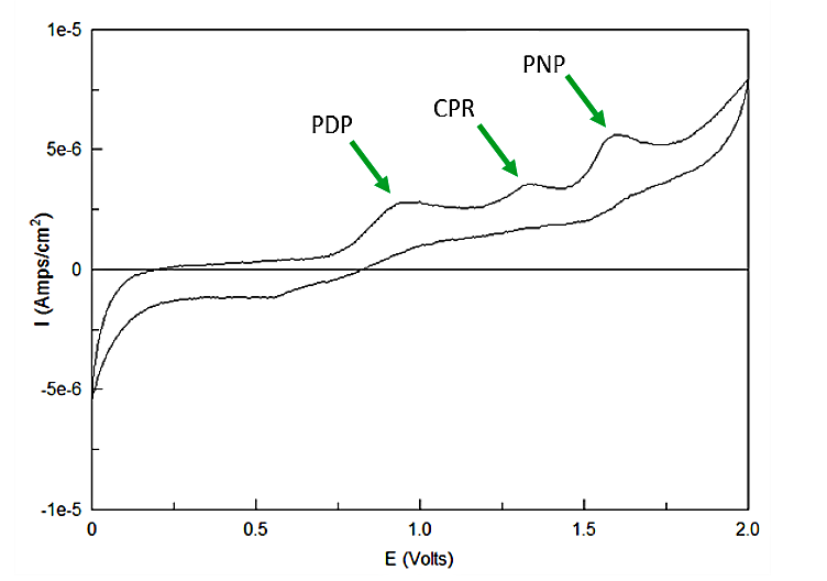
Out of the three sugar conjugates the only one that exhibits any electrochemical activity is PDPG, with it's oxidation potential at 0.6V vs. the reduction of hydrogen reference electrode (RHE). The three analytes have potentials at 0.825V for PDP, 1.325V for CPR, and 1.6V for PNP vs RHE. As none of these peaks overlap and no sugar conjugates interfere with their signals the three chemicals can be detected in the same solution. Figure 3 shows sensitive simultaneous detection of our three analytes with no background interference.
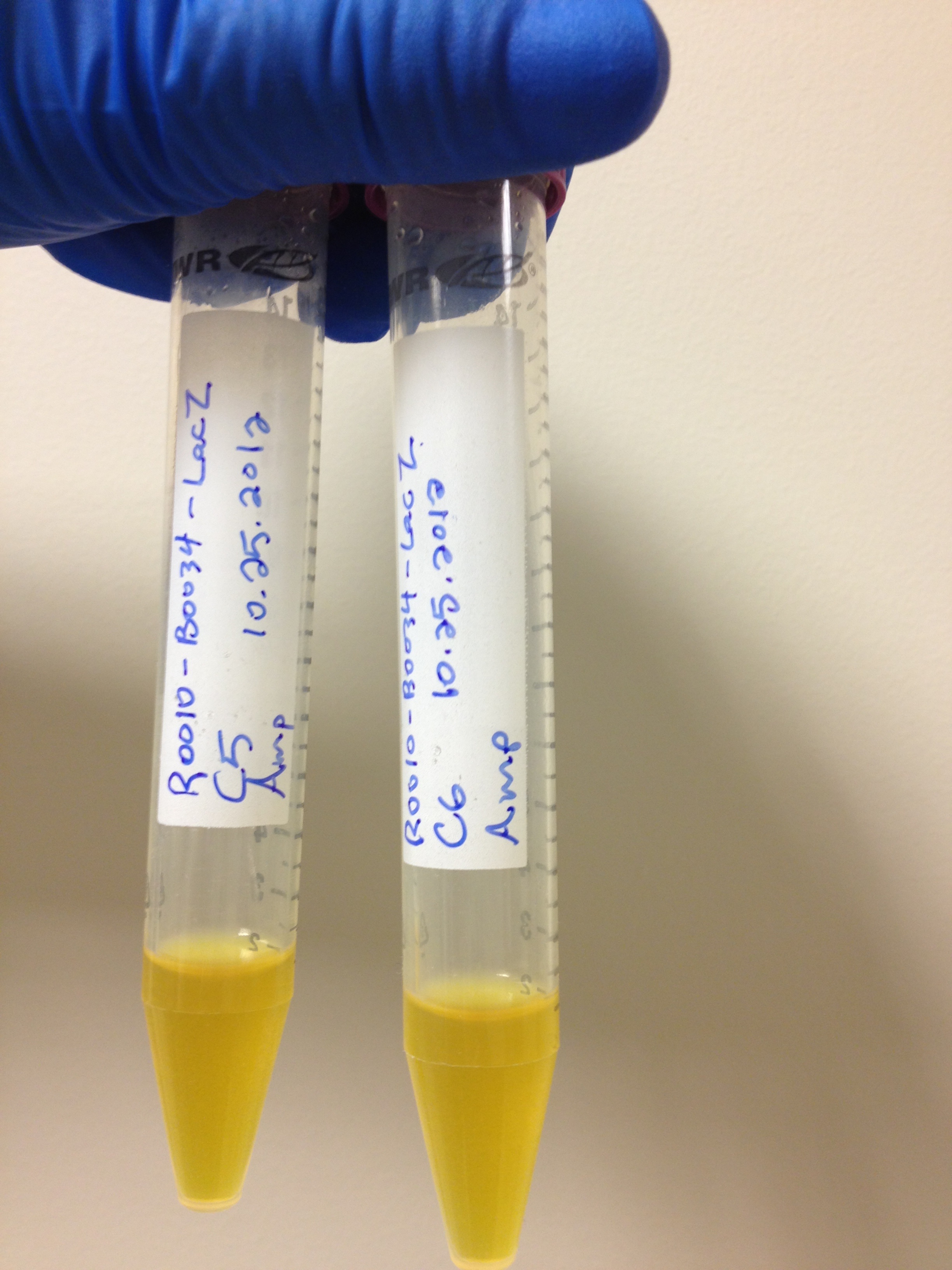
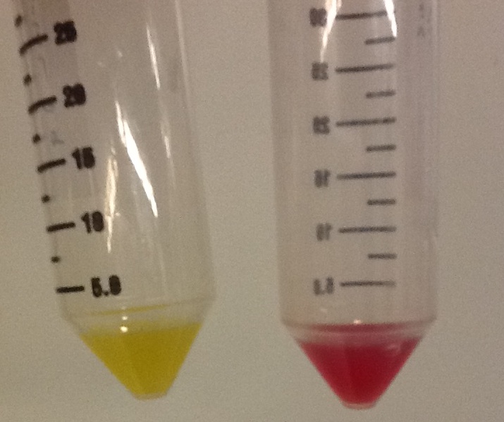
With the chemicals finalized we now needed to construct our circuits. There is a lacZ gene under the control of the lacI promoter in the registry already registry (BBa_I732901). Upon testing this circuit however, it was determined to not be functional. In a simple assay where we added CPRG to cells expressing this part and induced with 200 mM IPTG, we saw no color change, as we would have expected if the LacZ enzyme was being produced and cleaving the CPRG (yellow) into CPR (red). This can be seen below
.Sequencing of this part showed that it had a frameshift mutation. Original validation of our system was thus done using one of the constitutive lacZ hits from the transposon screen. After Regionals, a new circuit was constructed and submitted as BBa_K902090. A similar assay was performed and the results can be seen above as well. On the right is the new circuit, while on the left, the old circuit. The red color indicates that the new pat is indeed functional. This circuit was used in later testing using the LacZ enzyme. The bglX and uidA genes were amplified from the E. coli genome using PCR and biobricked as BBa_K902004 and BBa_K902000 respectively. These genes were then constructed under the lacI promoter to allow for comparison testing.
Does it Work?
Yes! We have been able to show that we can detect the action of our hydrolase enzymes acting on the sugar-conjugated compounds to give us an electrochemical signal (Figure 4).
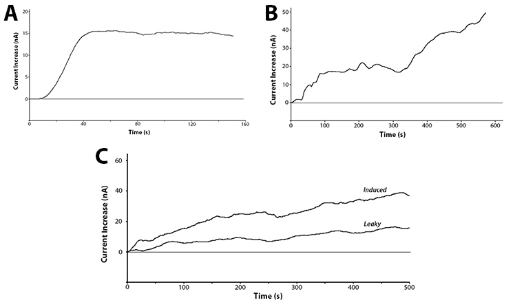
These graphs show two main points. The first being that we can successfully use hydrolase enzymes as reporters for gene expression with a sensitive output. This gives us the power to accurately watch bacteria respond to a stimuli in real time with the ability to differentiate between minute differences in expression strength. As these reporters do not rely on having a colour or fluorescence output they can be used in turbid solutions and even solutions free from oxygen. This removes two of the major limitations of current biosensors, allowing this branch of biotechnology to access a broad new market.
The second interesting conclusion that can be drawn for part C of Figure 4 is the leakiness of the BBa_R0010 promoter. The bacteria were induced at time zero and a clear increase is seen almost immediately for the induced trial, but the current does still increase over time for the uninduced test. The leaky expression of the genes downstream of this promoter could be detrimental in situations such as toxic gene expression or time dependent events.
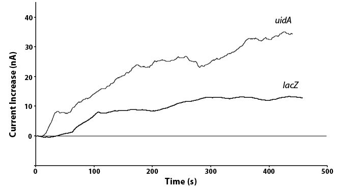
We have also been able to directly compare the lacZ and uidA circuits under the same promoter, as shown in Figure 5. In doing this we see twice the current in the uidA system as opposed to the lacZ system with the same conditions. This is because the analyte produced through the action of uidA produces a product that oxidizes to release two electrons while the lacZ product only releases one electron when oxidized. As the current we measure is this release of electrons, a similar amount of the two enzymes would results in the doubling of current for uidA that we saw, showing that our systems are working as expected.
What Next?
With our electrochemical system functioning properly we can now hook up our reporter genes to promoters found in the transposon library for a final detection system. We have also created a hardware and software platform for a field-ready biosensor. Our system has also been mathematically modeled in MATLAB to aid us in planning time courses for the experiments and the final prototype. When combined with the mechanical and biological containment mechanisms used in our system these genes create a novel and safe approach to biosensing in the oil sands and in many other potential applications.
 "
"
