Team:Calgary/Project/OSCAR/Bioreactor
From 2012.igem.org
Iaingeorge (Talk | contribs) |
Iaingeorge (Talk | contribs) |
||
| Line 27: | Line 27: | ||
<div align="center"> | <div align="center"> | ||
| - | <iframe width=" | + | <iframe width="600" height="480" align="center" src="http://www.youtube.com/embed/DVTR68DMi5U" frameborder="0" allowfullscreen></iframe> |
</div> | </div> | ||
| Line 33: | Line 33: | ||
<div align="center"> | <div align="center"> | ||
| - | <iframe width=" | + | <iframe width="600" height="480" align="center" src="http://www.youtube.com/embed/4onfIfuQJ9c" frameborder="0" allowfullscreen></iframe> |
</div> | </div> | ||
| Line 40: | Line 40: | ||
<p>'''Particle generated video using RealFlow2012'''</p> | <p>'''Particle generated video using RealFlow2012'''</p> | ||
<div align="center"> | <div align="center"> | ||
| - | <iframe width=" | + | <iframe width="600" height="480" align="center" src="http://www.youtube.com/embed/m4Lz6Z8HiQA" frameborder="0" allowfullscreen></iframe> |
</div> | </div> | ||
Revision as of 02:57, 3 October 2012
[http://www.example.com link title]


Hello! iGEM Calgary's wiki functions best with Javascript enabled, especially for mobile devices. We recommend that you enable Javascript on your device for the best wiki-viewing experience. Thanks!
Bioreactor: The House of OSCAR

Introduction
A major goal of our project was to use genetically engineered bacteria to convert toxic organic compounds into recoverable hydrocarbons. Accomplishing this goal required us to make a system that could support this biochemical process. The support system we chose was a bioreactor. Bioreactors are engineered vessels designed to help optimize a given biochemical process.
Some examples of large scale bioreactors are wastewater treatment plants, tissue engineering, and even beer fermentation. All of these systems, including ours, need proper heat and oxygen exchange as well as suitable pH and agitation control. With the addition of ideal flow rates, growth medium, and bacterial growth rates, we were left with many design considerations to go into our bioreactor.
In addition to looking into a bioreactor design, we were also tasked with finding a way of extracting the produced hydrocarbons from the bioreactor. Theoretically, the hydrocarbons being less dense and hydrophobic should settle in the top layer of the solution. Separation of a certain layer into various components can be done in many ways such as using a centrifuge or even various filters.
A bioreactor utilizing genetically engineered bacteria could have serious environmental implications if somehow the bacteria were to escape. Introducing something not meant to be in the environment has the possibility of having detrimental and irreversible effects. Thus, safety was a huge consideration throughout our project.
Research
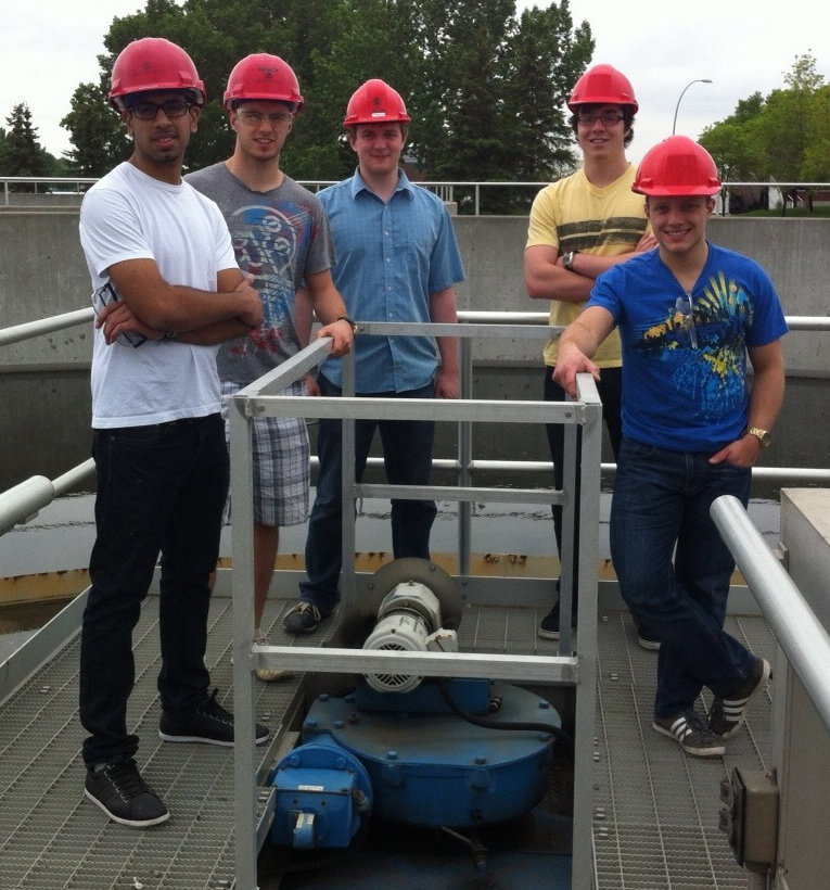
Before diving into a making bioreactor, we first had to research current solutions in the field. To help us with this phase, we read research papers on bioreactors, toured a wastewater treatment plant, interviewed graduate students in the field, and had weekly meetings with the supervisors and biologists on our team. The bioreactors at the wastewater treatment plant were contained in open systems since they used natural microbes. The reactor also contained an air sparger to oxygenate the solution and spun at an extraordinarily slow rate. This was one of the many bioreactor processes we looked into. Below are pictures from our trip!
Our Bioreactor Evolution
Throughout the year we worked on creating a prototype of the bioreactor. Our ideal process would be a fed-batch system, where the reactors would be continually fed with more bacterial nutrients and fresh tailings. The fresh tailing would be added when the naphthenic acid concentration within the bioreactor is lower, thus allowing the bacterium to continually convert naphthenic acid to hydrocarbons. Additionally, the process would have to occur within an enclosed system to ensure its sterility.

The Prototype
We determined a few basic concepts that needed to be included in the prototype. For one, we needed to make our bioreactor a closed system in order to keep our solution sterile. This is necessary to allow only our bacteria (E. coli with ampicillin resistant gene) growing in the tank to optimize its growing conditions. It is also necessary to reduce the risk of our bacteria escaping our tank.
Next, we needed to use a batch system for our system to work at lab scale (for competition data). This means that we are allowing the entire process to occur, and then removing all of our solution when our reactions have come to completion. This batch will include an appropriate growth medium and ampicillin to help our specific bacteria grow. This opposes a continuous stir method, where product is removed at the same rate that biomass and nutrients are added. A continuous method would be more appropriate at an industrial scale (1000+ L tanks), where the bacteria will have enough time to convert NA’s in such large tanks.
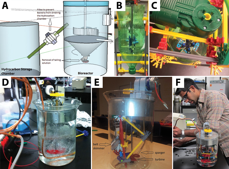
Furthermore, we had to find a way to remove the hydrocarbons once they were produced. We decided to use a belt skimmer, similar to those used to help clean up oil spills. This method is useful because it allows us to run the belt to pick up hydrocarbons without having to remove the entire solution of the batch. This way the bacterial culture already present in the tank can be reused to produce more hydrocarbons. To ensure no bacteria can escape from the bioreactor the belt skimmer will have a UV light attached across the belt to ensure any bacteria picked up dies before the hydrocarbons are skimmed from the bioreactor chamber.
Finally to ensure efficient bacterial growth we included both a sparger and a turbine in the bioreactors design. The purpose of the turbine was to mix the solution preventing the bacteria and other heavier materials from settling at the bottom of the vessel. The sparger oxygenated the solution providing the condition necessary for the aerobic bacteria to thrive. When assembled together the turbine would be located above the sparger thus breaking each bubble from the sparger into smaller ones. In a thicker solution such as tailings, both the air sparger and turbine will agitate the solution thus mixing it and prevent heavier materials from settling at the bottom of the chamber.
Once we had these designs in place, we were able to start building models and presentation material. One of our goals was to have a computer animation of our design in motion. We were able to meet this goal by using programs called Maya and RealFlow. Maya is a complex and extremely versatile computer animation program used for many animated movies, including James Cameron’s “Avatar”. RealFlow is a particle-generating program, used primarily for creating fluid flow and fluid effects. Combining both of these programs, we created a seventeen second long video showing the basic idea of how our bioreactor will work. In addition to this, we made a functioning model of a tank with our turbine, belt skimmer, and sparger included inside. Our model is also a closed system, which will be brought to the competition to demonstrate to the judges.
'''Particle generated video using RealFlow2012'''
'''First Maya Rendered Animation: Open System Showing Separation of Hydrocarbon Layer'''
'''Final Maya Rendered Animation: Closed System Showing Emulsified Hydrocarbons'''
Testing and Results
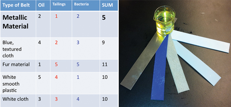
Using the physical models that we made, we were able to conduct experiments to help determine what will make our design most efficient. We received five different belt samples from a belt skimming company (Abanaki), so we conducted three different tests to determine which belt would work best for us. Our tests sought to find the belt that picked up the most oil, least tailing pond material, and least amount of bacteria.

Additionally, we ran three different twenty-four hour bacterial growth tests in our tank to determine the effectiveness of the agitator and sparger on bacterial growth. The test was conducted with a turbine and a sparger, only a turbine, and only a sparger. At the end of each experiment we measured the optical density of the solution with a spectrophotometer to quantify the bacterial growth. Operating our bioreactor with both a turbine and sparger resulted in slightly greater bacterial growth than just the turbine, which coincides with our hypothesis. The results are displayed below:

Also, we mixed water, commercial NA’s, and hexadecane (model hydrocarbon) together in a small test tube to determine if we will indeed get a top layer of hydrocarbons like what we need. Indeed, this top layer of hydrocarbons was formed after two minutes of time to allow for separation.
Next Steps
The next steps would include developing a feedback and sensing method to monitor the temperature, Ph, and C02 in a highly toxic and corrosive environment. Once the genetically engineered bacterium is produced we can start modeling the bacterial life cycle. Since our bacteria will only produce hydrocarbons within its stationary phase, we would like to look into increasing this portion of the lifecycle and possibly into adding bacteria to the bioreactor when it is in its exponential phase rather than the lag phase. This should reduce the time needed for each reactor cycle. Also, another important aspect we can test after the bacteria are made is the rate of hydrocarbon production by the bacteria.
References
[1] Asenjo J.A. (1949).Bioreactor system design. New York (NY): Marcel Dekker Inc.
[2] Reit K., & Tramper J. (1991). Basic bioreactor design. New York (NY):Marcel Dekker Inc.
 "
"
