Team:Bielefeld-Germany/Sewage treatment plant
From 2012.igem.org

Approach
One of the aims of the iGEM competition is to introduce groundbreaking ideas with the help of synthetic biology, which should be applicable in real world scenarios. The drawback of a possible iGEM project is the gap between academic research and industrial needs. Conventional industrial processes have to be compared to the potential application. Furthermore the potential application has to be compatible to existing structures, because the construction of new structures is cost-expensive and productivity-sapping as well. Our project deals with the possibility to introduce a cell free biological system to already existing engineered structures in sewage plants. To evaluate the possibilities of a real world application, we cooperated with three sewage treatment plants. To cover large-scale plants as well as smaller rural plants we visited the treatment plant [http://www.route-industriekultur.de/themenrouten/13-auf-dem-weg-zur-blauen-emscher/klaeranlage-bottrop.html Emscher Kläranlage Bottrop] with a population equivalent of 1.3m, the treatment plant [http://www.obere-lutter.de/ Obere Lutter] in Gütersloh with a population equivalent of over 300,000 and the treatment plant [http://www.schlossholtestukenbrock.de/060/sr_seiten/artikel/112120100000015850.php Schloß Holte-Stukenbrock] with a population equivalent of about 30,000. We discussed the project with the plant managers Mr. Holtmeier (Emscher Kläranlage Bottrop) Mr. Burbaum (Obere Lutter) and Mr. Bülter (Schloß Holte-Stukenbrock). Together we were looking for potential operational sites for our immobilized laccases within the different stages of treatment to eliminate estrogen and other aromatic compounds from the waste water. We were discussing about advantages, limitations and problems, that could arise. We would like to thank Mr. Holtmeier, Mr. Burbaum and Mr. Bülter for all their great ideas, their inspiration and for all the time, they invested.
Introduction
Sewage is generated every day by everyone. Therefore efficient sewage treatment is absolutely necessary to guarantee the quality of surface water, ground water and of course of drinking water. However sewage is often heterogeneous and consists of liquids from toilets, kitchen, sinks as well as liquids from industrial processes and commercial use. Therefore sewage treatment plants have to consist of various treatment stages. The general composition of a large-scale treatment plant is shown in the flow diagram in Figure 1.
Functional principle
Schematic
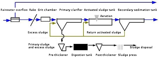
We visited the large-scale sewage treatment plant “Obere Lutter” which is located near Gütersloh and which is equipped with three sewage stages. The different stages will be explained in the following section.
Primary treatment: mechanical stage
The first step in sewage treatment is the retaining of rude solids with rakes. Grates directly behind the rakes hinder swimming solids. The intake pumping station transports the water to the grit chamber and the primary clarifier at a slightly higher level. The grit chamber is also used to remove fat. The trapeziform cross section and aeration with air support the sedimentation of sand, although organic solid remain in the water. Sediment is removed with special movable plates and after washing and drying the sand can be used in road building. The Primary clarifier is the last step in the mechanical cleaning and works with sedimentation, too. In modern sewage treatment plants primary clarifier are rarely used because they lower the concentration of easy biodegradable substances, which are necessary for denitrification. The mechanical stage is also called primary treatment.
Secondary treatment: first biological stage
In the first biological stage, the so called secondary treatment, the organic content of the sewage is considerably reduced by the use of microorganisms. Most organic content are carbon, nitrogen or phosphorous compounds. Depending on tank number and design nitrification and denitrification can take place simultaneously or intermittent. The intermediate clarifier is used to remove the activated sludge with the help of return sludge pumps. For phosphorus removal chemical precipitation can be used through addition of iron salts. Also salts can be added if pH adjustment is necessary.
Secondary treatment: second biological stage
In the second biological stage compensation tanks are used to retent surplus water if the flow rate gets too large. Before the waste water is directed into another denitrification tank it gets lifted by a pump station. So the water can flow in a free gradient through the second biological stage. The second denitrification upstream to the actived sludge tank works with microorganism to further degrade nitrate compounds to elementary nitrogen. The operation procedure of the second activated sludge tank is similar to the sludge tanks used in the primary biological stage, but the tanks differ in size and flow rate. Therefore dimensions of the surface aeration are adjusted. Calcium carbonate may be added to adjust the pH.
Tertiary treatment: fourth purification stage
The fourth purification stage or so called tertiary treatment provides a further improvement of the effluent quality. After having passed the maturation pond the water is discharged into the environment, for example in the sea, in rivers, lakes, ground, etc.) The fixed bed dentrification lowers the concentration of nitrogen compounds with the use of biological elimination. The fixed bed works as an artificial surface for microorganisms to grow. As carbon source methanol may be added. The fixed bed consists of expanded clay, for example. Supporting flint layer provide the stability.
Floccation filtration is used to eliminate soluble phosphate based compounds. Upstream addition of iron salts causes precipitation of the phosphates as insoluble compounds. The filtration is aerated, air and wastewater flow co-current through the filter. Attached microorganisms and aeration cause nitrification, but aeration is also needed to eliminate the added methanol. The most common floccation filtration uses Biolit (stone powder) as fixed bed. The use of activated carbon is an arising application because activated carbon also eliminates micro-contaminants like pharmaceutical used compounds. For more information about the common floccation filtration methods click The new innovation: immobilized laccases.
Sludge treatment: utilization and disposal
The biggest waste product of a sewage treatment plant is the remaining sludge. It is part of the waste water, but is also generated in the activated sludge tanks. In wastewater treatment plants the sludge is continuously pumped into digestion tanks. Via anerobic digestion the remaining organic compounds are hydrolysed via hydrolysis, acidogenesis and methanogenesis to water, carbon dioxide, methan and hydrogen. The biogas can further be use in electricity generation or for heating purposes. The remaining sludge is for example thickened, pressed and afterwards disposed via burning.
The new innovation: Immobilized Laccases
New potential applications always have to be compared to conventional industrial processes. Ideal preconditions for the implementation of a new application are existing structures for the use of the application as well as better performance compared to the conventional methods. The cost comparison is another important part of the implementation. In the following section we will therefore compare the conventional methods with our system. Conventional methods use physico-chemical properties or living biological systems to decrease pollution and to eliminate specific compounds. In contrast to this our system uses immobilized laccases, able to break down aromatic structures, to degrade to microcontaminants such as ethinylestradiol and other phenolic substances.
Conventional floccation filtration with Biolit

The most commonly used system for fixed bed floccation filtration is a system using ‘’Biolit’’, a stone powder. The fixed bed is supported with flint layers. The process combines filtration with biological carbon reduction and denitrification. The system is further used for elimination of phosphate based compounds. The functional principle is based on attached microorganisms. Therefore aeration is required. Aromatic compounds such as estrogens and steroid hormones as well as most residual pharmaceutical substances cannot be eliminated. Furthermore the use of attached microorganisms results in free-floating cells, which need to be filtered before using the water as drinking water.
Floccation filtration with activated carbon
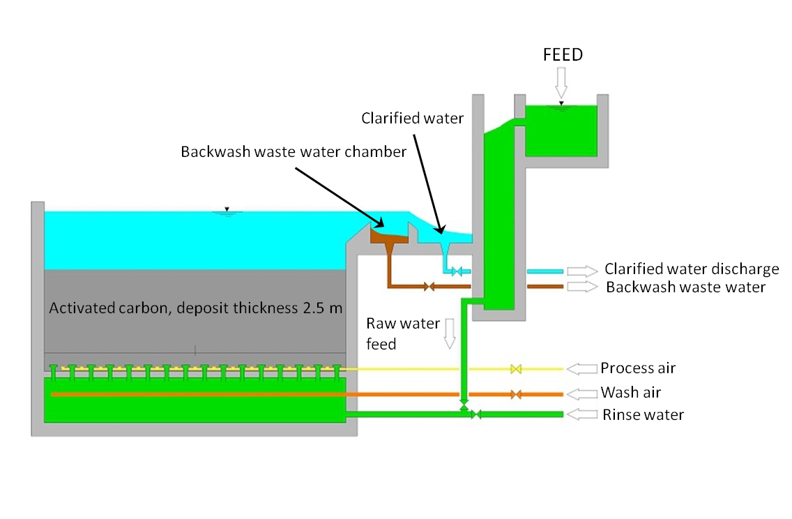
Recently activated carbon was used to replace the ‘’Biolit’’. The functional principle of activated carbon is based on its properties for adsorption. By using activated carbon the concentration of chemicals as chlorine as well as hormones and pharmaceutical substances can be reduced. But the capacity for removing pollutants depends on the surface area of the carbon. The longer the activated carbon is used, the weaker the adsorption gets. If the occupancy rate is too high, the activated carbon has to be removed and replaced. Reactivation and regeneration of the carbon is very expensive. The most commonly used method is desorption under high temperatures (500 – 900 °C). Alternatively the carbon can be burnt, but the acquirement of activated carbon is expensive as well. Mr. Burbaum of the treatment plant in Gütersloh puts the costs for the use of activated carbon at up to 2300 $ per ton for new activated carbon and up to 1600 $ per ton for reactivated carbon. The resulting costs for a treatment plant with a population equivalent of 300K can be estimated at up to 500000 $ per year.
A new approach: Immobilized Laccases
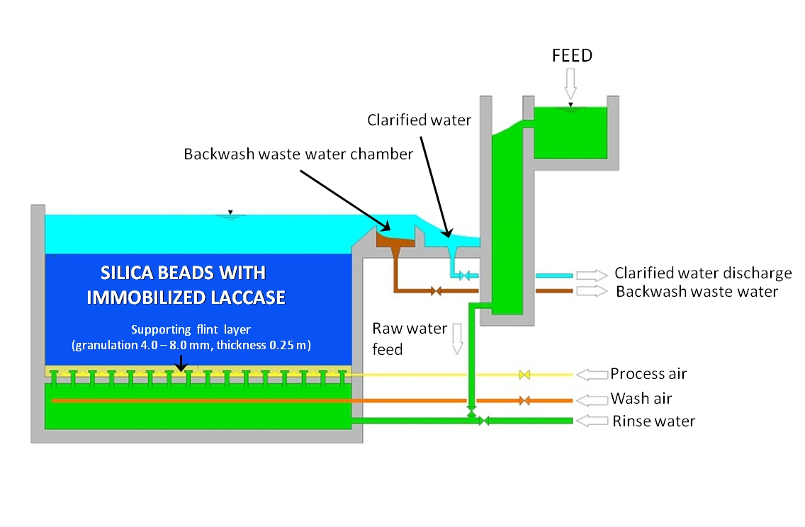
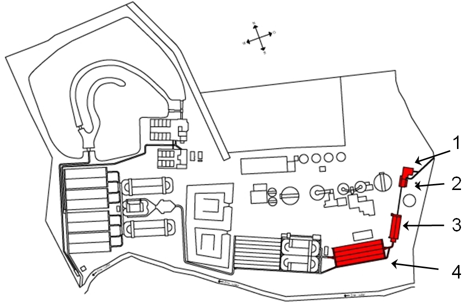
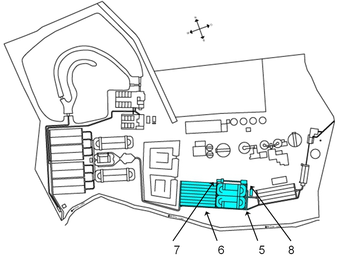
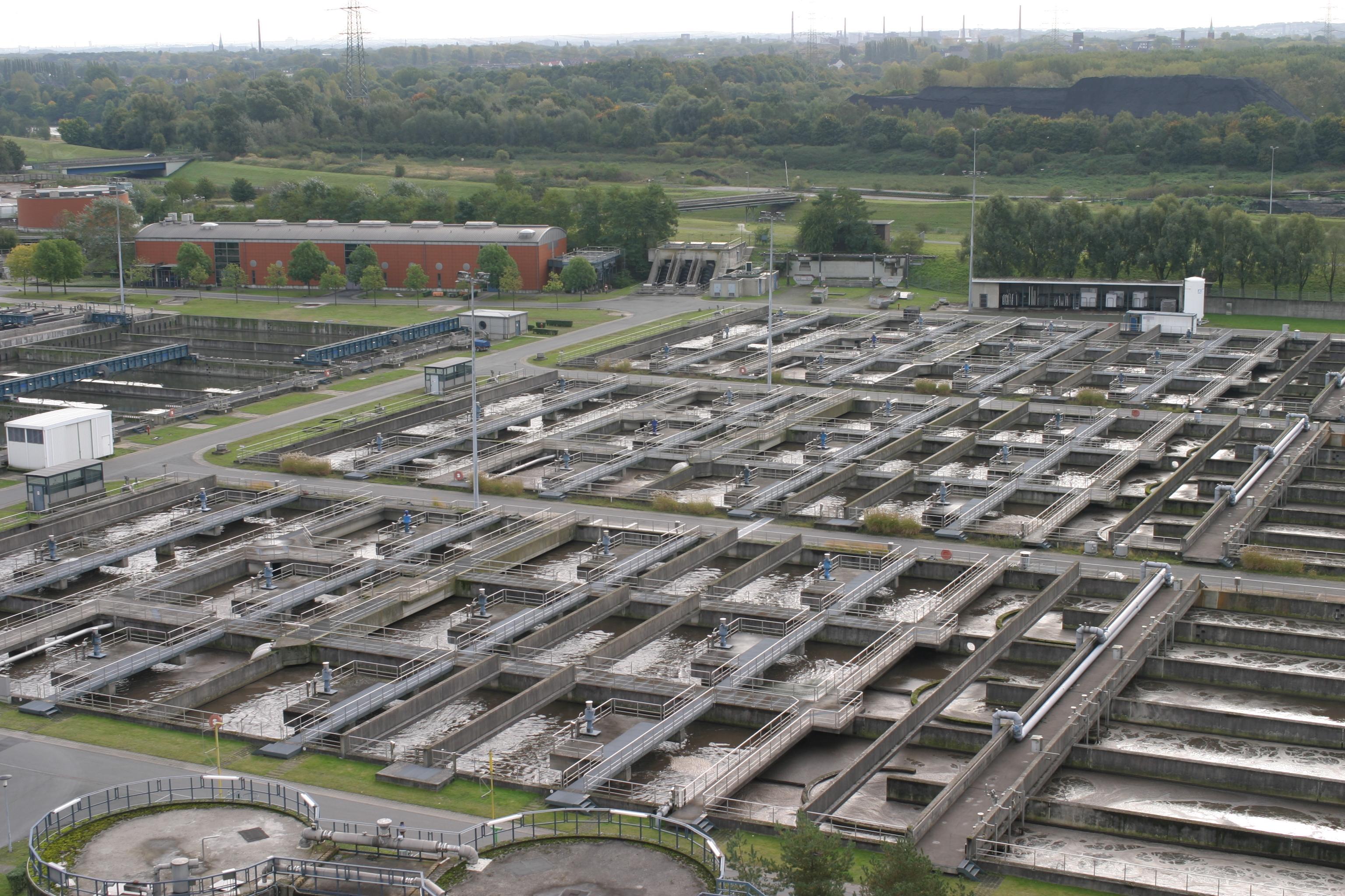
After having visited the sewage treatment plants we discussed with Mr. Holtmeier, Mr. Burbaum and Mr. Bülter about potential, already existing structures that could be used for degradation of aromatic compounds with immobilized laccases. The best suited locations are shown with red arrows in the figures 5 and figure 6. The activated sludge tank (figure 5) is equipped with a fine meshed filter, large particles stay in the tank. Therefore the beads need to have a diameter of 5 mm, at least. Consequently silica beads cannot be used. Besides silica beads would sediment very fast. Another problem is the heterogeneous microorganism population. Emerging formation of biofilms would not only cover the beads but also hydrolyze the immobilized laccases. As a result the enzyme activity would decrease fast.
The better possibility is a fixed bed flocculation filtration tank filled with beads instead of activated carbon or ‘’Biolit’’. Additional supporting flint layers would minimize the discharge. Flushing with a bottom-up flow also guarantees a long exposure time. Additional layers of activated carbon may further increase the range of compounds which can be eliminated. Figure 10 shows a schematic drawing of a possible fixed bed tank with immobilized laccases. The intake of process air, wash air and rinse water offers the possibility to adjust physical properties for example the pH value to optimize the enzyme activity.
Before using the system, assessment research has to be done. Degradation products of various substrates have to be quantified. The variation of the enzyme activity has to be measured over time. Finally the optimal enyzme concentration and the best filling level of the tank have to be adjusted. Finally only a cost estimation could compare our project to conventional methods of fixed bed tanks.
Expert evaluation
In our discussions with Mr. Holtmeier, Mr. Burbaum and Mr. Bülter, we were encouraged that our project might be a realistic alternative to conventional systems of eliminating micro contaminants such as steroid hormones and pharmaceutical compounds. Mr. Burbaum agreed with us that the contamination of drinking, ground and surface water with micro contaminants is a problem, which is even getting worse. Only large-scale treatment plants can possibly build up structures to eliminate the compounds in systems like fixed bed tanks filled with activated carbon. In smaller rural treatment plants often only two treatment stages exist. Therefore no structures could possibly be used for treatment with activated carbon or even with immobilized laccases. Cost-intensive construction projects are needed to face the problem of increasing concentrations of micro contaminants. Even on governmental level official consider various possibilities of solving the problem. Another problem is the limit of detection when it comes to steroid hormones. Often the no effect level is way smaller then the detection limit, therefore the consequences of permanent exposure can only hardly be measured.
Investigation of potential operational sites in treatment plants without tertiary treatment stage
In the following section two different sewage treatment plants are observed for potential operational sites of our system using laccases to eliminate estrogen derivates and other phenolic compounds. A special characteristic of the two following treatment plants is the absence of a tertiary treatment stage. Due to lacking systems like flocculation filtration other operational sites have to be identified for the use of immobilized laccases. The sewage treatment plant [http://www.route-industriekultur.de/themenrouten/13-auf-dem-weg-zur-blauen-emscher/klaeranlage-bottrop.html Emscher Kläranlage Bottrop] is one of the biggest treatment plants within Europe, therefore tertiary waste treatment is unsuitable because of the immense water flow-through. The sewage treatment plant of [http://www.schlossholtestukenbrock.de/060/sr_seiten/artikel/112120100000015850.php Schloß Holte-Stukenbrock] is a small rural plant, which is only used for the clarification of waste water from private households. Therefore only few industrial contaminations can be found in the water. But most pharmaceutical contaminations in waste water are generated by private households, requiring an efficient system to eliminate phenolic compounds. So in order to identify potential operational sites we visited both treatment plants and discussed our project with the treatment plant managers.
Sewage treatment plant: [http://www.route-industriekultur.de/themenrouten/13-auf-dem-weg-zur-blauen-emscher/klaeranlage-bottrop.html Emscher Kläranlage Bottrop]
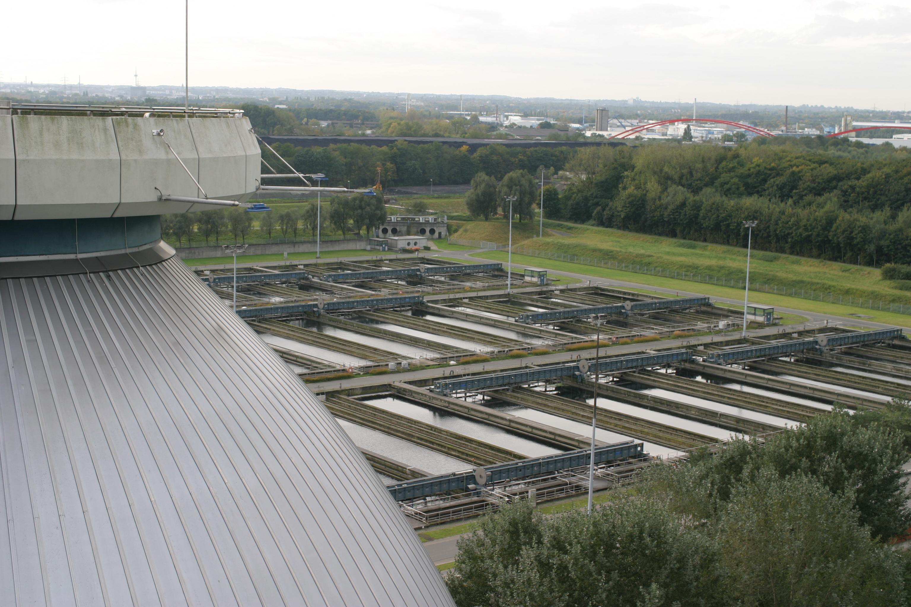
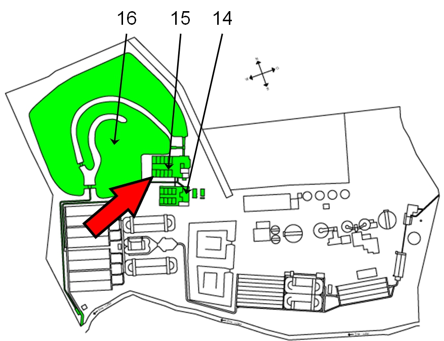
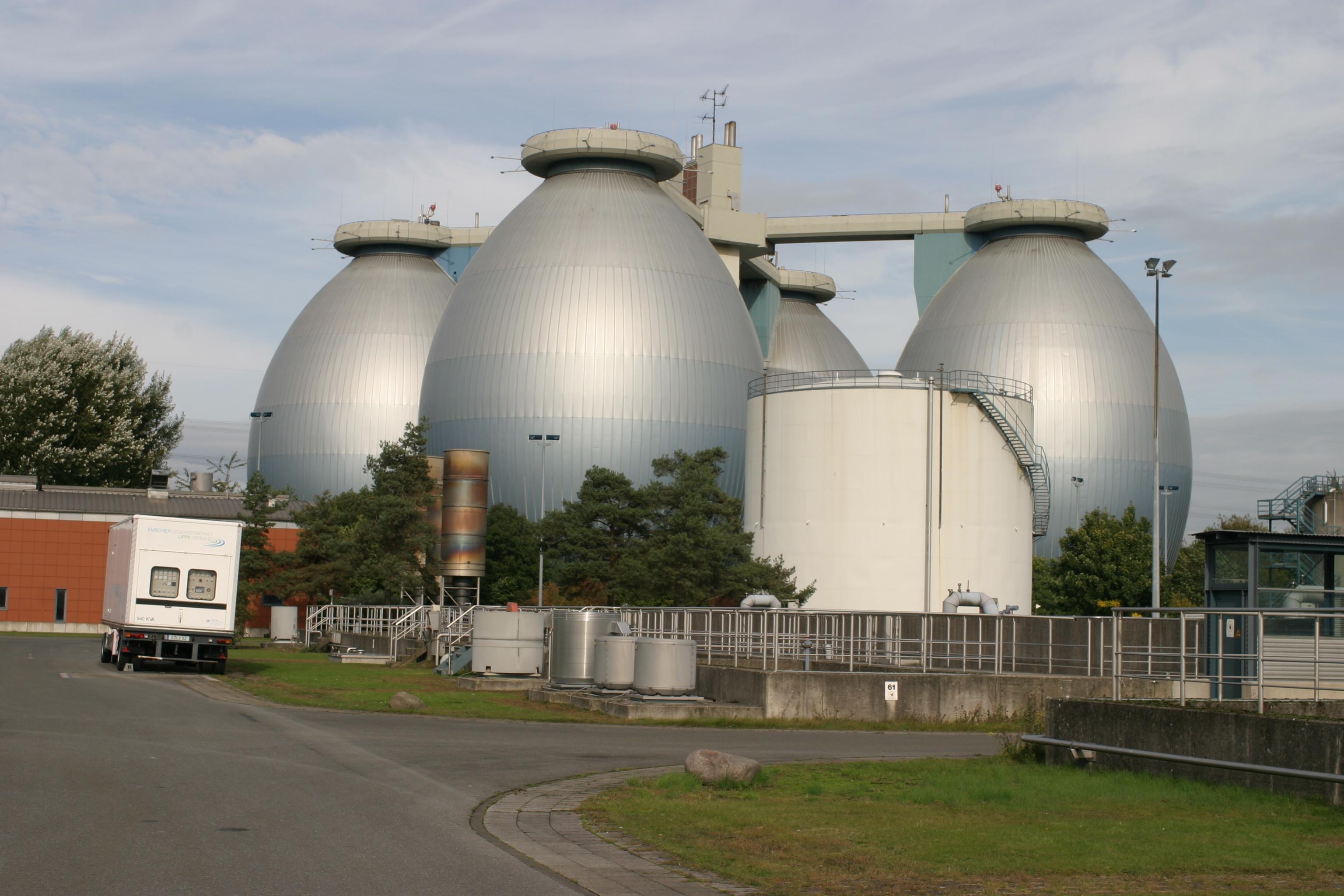
The sewage treatment plant [http://www.route-industriekultur.de/themenrouten/13-auf-dem-weg-zur-blauen-emscher/klaeranlage-bottrop.html Emscher Kläranlage Bottrop] is one of the biggest German treatment plants with a population equivalent of 1.3 million. The digestion tanks have a total volume of 60,000 m³, making them the biggest digestion tank system in the world. The water flow of the treatment plant is ~8.5 m³ s-1. When we visited the plant, we found that the treatment plant is equipped with two biological treatment stages but lacks a tertiary treatment stage. Still the implementation of our system can be achieved by adding a metal sieve to the secondary clarifiers (shown in figure 13). The metal sieves would be filled with beads (with immobilized laccases), preventing the beads from sedimenting in the tanks. By adding the metal sieves to existing movable plates a constant mixing can be guaranteed. The plates are normally used for the transportation and removal of sedimented solids. Due to the slow movement of the plates (and thus the metal sieves) a long contact time of immobilized laccases and surrounding water is obtained.
Sewage treatment plant: [http://www.schlossholtestukenbrock.de/060/sr_seiten/artikel/112120100000015850.php Schloß Holte-Stukenbrock]

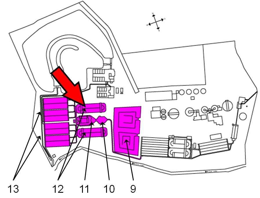
We also visited the sewage treatment plant of [http://www.schlossholtestukenbrock.de/060/sr_seiten/artikel/112120100000015850.php Schloß Holte-Stukenbrock], which is a small rural treatment plant with a population equivalent of 30,000. Only little industrial waste water has to be treated. The plant is only equipped with two treatment stages. Therefore an implementation of our system is difficult, no structures for fixed bed tanks do exist. After the discussion with Mr. Bünter we agreed that a cellulose-based filter system with lassases immobilized through a cellulose binding domain could decrease the concentration of micro contaminants in the water. The potential placement of the filter is shown on figure 14 (shown as number 9 within the figure). The filter would be located right behind the treatment plant. Therefore we are constructing cellulose binding domains. Fusion enzymes with laccases could probably be used in a cellulose based filter.
Conclusion
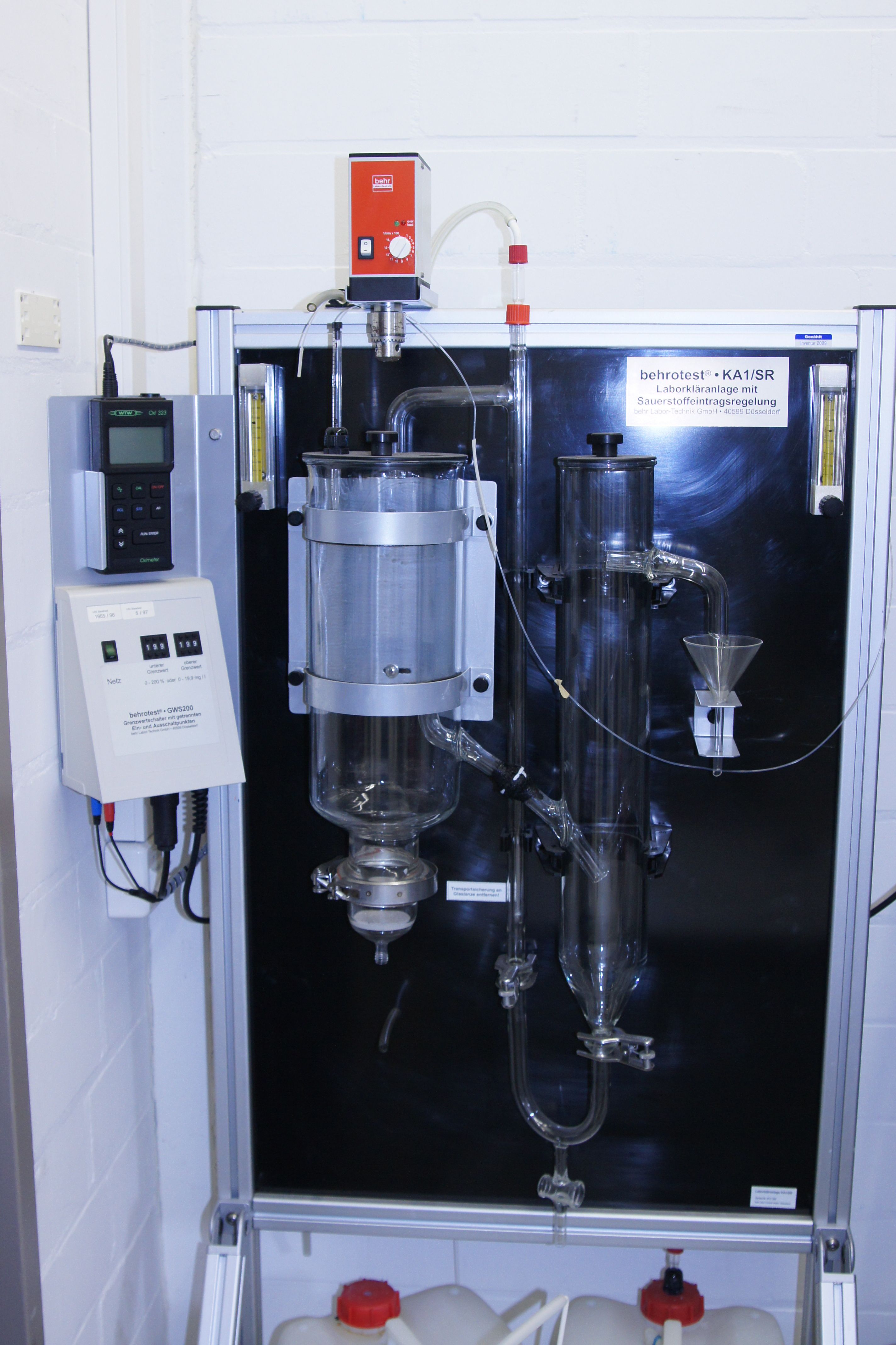
After evaluating our project with the three plant managers we think that we can provide a realistic alternative to commonly used systems for elimination of micro contaminants. Our system uses laccaces immobilized either on beads or on cellulose and can easily be implemented into different stages of waste water treatment. Many large-scale treatment plants already implement fixed bed flocculation filtration into the treatment. Therefore the operational structures for an industrial scale-up of our application already exist. No further costs for the construction of new structures would arise. Also we were offered the chance to test our project in a small system in a real plant under strict safety regulation. Before we test our system in an actual plant we plan to use a lab-scale waste water system (behrotest KA 1/SR, figure 12) to measure the enzyme activity of our immobilized laccases in active sludge and in a fixed bed reactor. The leakage of the enzymes and the stability of the immobilization have to be tested under realistic conditions. [http://www.vti.bund.de/en/startseite/institutes/fisheries-ecology/staff/dipl-biol-nicolai-fricke.html Nicolai Fricke], an expert of the [http://www.vti.bund.de/de/startseite/institute/foe.html Johann Heinrich von Thünen-Institute of Fisheries Ecology] noted, that many marine systems are very fragile. No one can predict the consequences of a collapsing big marine ecological system. Even the costs and the influence on the local economy can hardly be predicted. Even higher costs and an unfavorable cost-benefit evaluation of an alternative system for waste water treatment may be acceptable to prevent dramatic ecological problems. See all the notes of Nicolai Fricke concerning the impact of steroid hormones on marine ecological systems here.
References
Schloß Holte-Stukenbrock, http://www.schlossholtestukenbrock.de/060/sr_seiten/artikel/112120100000015850.php, on www.schlossholtestukenbrock.de, Sep 10, 2012
Mikroverunreinigungen, http://www.mikroverunreinigungen.de/obere-lutter/, on www.Mikroverunreinigungen.de, Aug 17, 2012
Obere Lutter, http://www.obere-lutter.de/das-klaerwerk/, on www.obere-lutter.de, Aug 5, 2012
Route Industriekultur, http://www.route-industriekultur.de/themenrouten/13-auf-dem-weg-zur-blauen-emscher/klaeranlage-bottrop.html, on http://www.route-industriekultur.de, Oct 26, 2012
| 55px | | | | | | | | | | |
 "
"


