Team:NTU-Taida/Modeling/System-Analysis
From 2012.igem.org
(→Threshold of Our High Pass Filter) |
Monkey781213 (Talk | contribs) (→Protein Degradation Rate) |
||
| (30 intermediate revisions not shown) | |||
| Line 27: | Line 27: | ||
===Protein Production Rate=== | ===Protein Production Rate=== | ||
<html><ol style="list-style-type: lower-latin;"> | <html><ol style="list-style-type: lower-latin;"> | ||
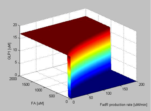
| - | <li style="font-weight : bold; margin-top:20px">alpha_FadR</li></html><br />[[File:Team-NTU-Taida-Sys_f1.png|center|350px]]<br /><br/>When the FadR production rate is zero, there is no FadR existing in the cell, and therefore TetR is not repressed, resulting in the expression of GLP1 in high level regardless of the FA concentration. After the FadR production rate goes above a threshold not far from 0, sharp transitions between the maximum level of GLP1 and zero appears, as shown by the rainbow-color, nearly vertical plane. The FA value of the intersection between the vertical plane and the ground horizontal plane is the value of FA that triggers the system to produce GLP1, and therefore can represent the filtering threshold of our circuit. FadR production rate affects the value of the threshold dramatically as can be seen by the shifts of the intersection between the vertical plane and horizontal plane rapidly to higher FA values as the production rate increases. The result can be more clearly seen when plotting the y-z cut plane with different FadR production rate values on the same two-dimensional figure, as shown in Figure 9 in the next section.<html> | + | <li style="font-weight : bold; margin-top:20px">alpha_FadR</li></html><br />[[File:Team-NTU-Taida-Sys_f1.png|center|350px|thumb|Figure 1]] |
| + | <br /><br/>When the FadR production rate is zero, there is no FadR existing in the cell, and therefore TetR is not repressed, resulting in the expression of GLP1 in high level regardless of the FA concentration. After the FadR production rate goes above a threshold not far from 0, sharp transitions between the maximum level of GLP1 and zero appears, as shown by the rainbow-color, nearly vertical plane. The FA value of the intersection between the vertical plane and the ground horizontal plane is the value of FA that triggers the system to produce GLP1, and therefore can represent the filtering threshold of our circuit. FadR production rate affects the value of the threshold dramatically as can be seen by the shifts of the intersection between the vertical plane and horizontal plane rapidly to higher FA values as the production rate increases. The result can be more clearly seen when plotting the y-z cut plane with different FadR production rate values on the same two-dimensional figure, as shown in Figure 9 in the next section.<html> | ||
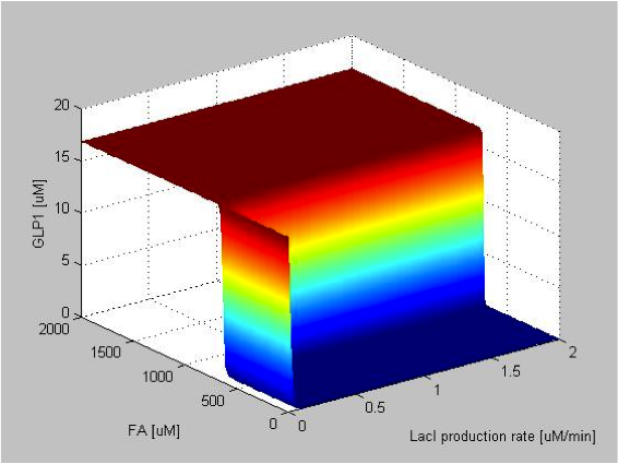
| - | <li style="font-weight : bold; margin-top:20px">alpha_LacI</li></html><br />[[File:Team-NTU-Taida-Sys_f2.png|center|350px]]<br /><br />When the LacI production rate is zero, there is no LacI present in the cell, which means that GLP-1 is not repressed. So that GLP-1 remains high at this value regardless of FA concentration. After the LacI production rate goes above a threshold very close to 0, sharp transitions between the maximum level of GLP1 and zero appears. We can observe that above the threshold the GLP-1 response is very robust to the change in LacI production rate, maintaining the constant maximum GLP1 level as the LacI production rate varies. LacI production rate has no significant effect on the value of the threshold as can be seen by the almost constant FA value of the intersections between the vertical plane and horizontal plane as the production rate increases. The result can be more clearly seen in the corresponding 2D figure.<br><html> | + | <li style="font-weight : bold; margin-top:20px">alpha_LacI</li></html><br />[[File:Team-NTU-Taida-Sys_f2.png|center|350px|thumb|Figure 2]]<br /><br />When the LacI production rate is zero, there is no LacI present in the cell, which means that GLP-1 is not repressed. So that GLP-1 remains high at this value regardless of FA concentration. After the LacI production rate goes above a threshold very close to 0, sharp transitions between the maximum level of GLP1 and zero appears. We can observe that above the threshold the GLP-1 response is very robust to the change in LacI production rate, maintaining the constant maximum GLP1 level as the LacI production rate varies. LacI production rate has no significant effect on the value of the threshold as can be seen by the almost constant FA value of the intersections between the vertical plane and horizontal plane as the production rate increases. The result can be more clearly seen in the corresponding 2D figure.<br><html> |
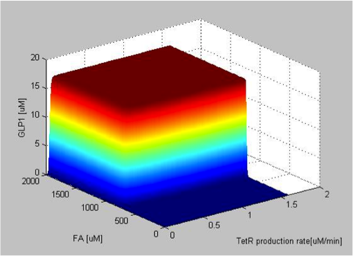
| - | <li style="font-weight : bold; margin-top:20px">alpha_TetR</li></html><br />[[File:Team-NTU-Taida-Sys_f3.png|center|350px]]<br /><br />When the TetR production rate is zero, there is no TetR present in the cell, so that LacI is not repressed and is free to block the expression of GLP1. Therefore, there are no GLP1 expressed despite of the high FA input. As soon as the production rate becomes non-zero, the production of GLP1 appears abruptly and with sharp threshold. The maximum level of GLP1 expression stays at a constant value with varying TetR production rate, indicating that the expression of GLP1 is able to resist fluctuations in TetR production rate. It can be seen that the threshold of FA filter varies very little with varying TetR production rate, as can be seen by the almost constant FA value of the intersections between the vertical plane and horizontal plane as the TetR production rate increases.<br><html> | + | <li style="font-weight : bold; margin-top:20px">alpha_TetR</li></html><br />[[File:Team-NTU-Taida-Sys_f3.png|center|350px|thumb|Figure 3]]<br /><br />When the TetR production rate is zero, there is no TetR present in the cell, so that LacI is not repressed and is free to block the expression of GLP1. Therefore, there are no GLP1 expressed despite of the high FA input. As soon as the production rate becomes non-zero, the production of GLP1 appears abruptly and with sharp threshold. The maximum level of GLP1 expression stays at a constant value with varying TetR production rate, indicating that the expression of GLP1 is able to resist fluctuations in TetR production rate. It can be seen that the threshold of FA filter varies very little with varying TetR production rate, as can be seen by the almost constant FA value of the intersections between the vertical plane and horizontal plane as the TetR production rate increases.<br><html> |
</ol></html> | </ol></html> | ||
===Protein Degradation Rate=== | ===Protein Degradation Rate=== | ||
<html><ol style="list-style-type: lower-latin;"> | <html><ol style="list-style-type: lower-latin;"> | ||
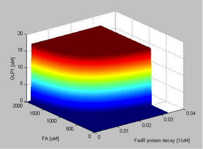
| - | <li style="font-weight : bold; margin-top:20px">gamma_FadR</li></html><br />[[File:Team-NTU-Taida-Sys_f4.png|center|350px]]If the FadR degradation rate is very low, the concentration of FadR will be higher thus blocking the synthesis of TetR. GLP1 express the maximum expression level at lower FA input concentrations as the FadR degradation rate increases. However, the maximum level of GLP expression is unaffected by the varying FadR degradation rate. When the FadR degradation rate is very high, FadR is degraded almost instantly after it is produced so that FadR is almost absent in the cell. Therefore TetR will not be repressed as long as the concentration of FA exceeds a small level, resulting in a low input threshold.<html> | + | <li style="font-weight : bold; margin-top:20px">gamma_FadR</li></html><br />[[File:Team-NTU-Taida-Sys_f4.png|center|350px|thumb|Figure 4]]<br /><br />If the FadR degradation rate is very low, the concentration of FadR will be higher thus blocking the synthesis of TetR. GLP1 express the maximum expression level at lower FA input concentrations as the FadR degradation rate increases. However, the maximum level of GLP expression is unaffected by the varying FadR degradation rate. When the FadR degradation rate is very high, FadR is degraded almost instantly after it is produced so that FadR is almost absent in the cell. Therefore TetR will not be repressed as long as the concentration of FA exceeds a small level, resulting in a low input threshold.<html> |
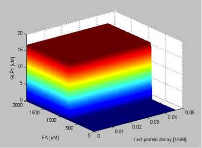
| - | <li style="font-weight : bold; margin-top:20px">gamma_LacI</li></html><br />[[File:Team-NTU-Taida-Sys_f5.png|center|350px]]The degradation rate of LacI follows a similar pattern as the production rate of TetR. If the LacI degradation rate is very low, the concentration of LacI will be higher, directly blocking synthesis of GLP1. The maximum level of GLP1 is not sensitive to variations of LacI degradation rates and neither is the filtering threshold.<html> | + | <li style="font-weight : bold; margin-top:20px">gamma_LacI</li></html><br />[[File:Team-NTU-Taida-Sys_f5.png|center|350px|thumb|Figure 5]]<br /><br />The degradation rate of LacI follows a similar pattern as the production rate of TetR. If the LacI degradation rate is very low, the concentration of LacI will be higher, directly blocking synthesis of GLP1. The maximum level of GLP1 is not sensitive to variations of LacI degradation rates and neither is the filtering threshold.<html> |
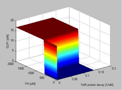
| - | <li style="font-weight : bold; margin-top:20px">gamma_TetR</li></html><br />[[File:Team-NTU-Taida-Sys_f6.png|center|350px]]If the TetR degradation rate is very low, the concentration of TetR will be higher, thus indirectly facilitating the synthesis of GLP1, as can be seen by the constant high value of GLP1 expression independent of the FA concentration when the degradation rate of TetR is zero. The filtering threshold is not sensitive to variations of the TetR degradation rate. <html> | + | <li style="font-weight : bold; margin-top:20px">gamma_TetR</li></html><br />[[File:Team-NTU-Taida-Sys_f6.png|center|350px|thumb|Figure 6]]<br /><br />If the TetR degradation rate is very low, the concentration of TetR will be higher, thus indirectly facilitating the synthesis of GLP1, as can be seen by the constant high value of GLP1 expression independent of the FA concentration when the degradation rate of TetR is zero. The filtering threshold is not sensitive to variations of the TetR degradation rate. <html> |
</ol></html> | </ol></html> | ||
===Repression Coefficient=== | ===Repression Coefficient=== | ||
<html><ol style="list-style-type: lower-latin;"> | <html><ol style="list-style-type: lower-latin;"> | ||
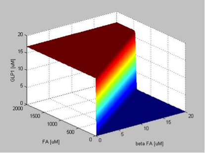
| - | <li style="font-weight : bold; margin-top:20px">beta_FA</li></html><br />[[File:Team-NTU-Taida-Sys_f7.png|center|350px]]The repression coefficient of FA describes the concentration of fatty acid needed to reduce the repression activity of FadR to half of its maximum value. Therefore, with higher repression coefficient of FA, we need more fatty acid to enable the expression of TetR1, therefore resulting in a higher filter threshold. We can see from the figure that the effect of the repression coefficient of FA on the threshold is very dramatic.<html> | + | <li style="font-weight : bold; margin-top:20px">beta_FA</li></html><br />[[File:Team-NTU-Taida-Sys_f7.png|center|350px|thumb|Figure 7]]The repression coefficient of FA describes the concentration of fatty acid needed to reduce the repression activity of FadR to half of its maximum value. Therefore, with higher repression coefficient of FA, we need more fatty acid to enable the expression of TetR1, therefore resulting in a higher filter threshold. We can see from the figure that the effect of the repression coefficient of FA on the threshold is very dramatic.<html> |
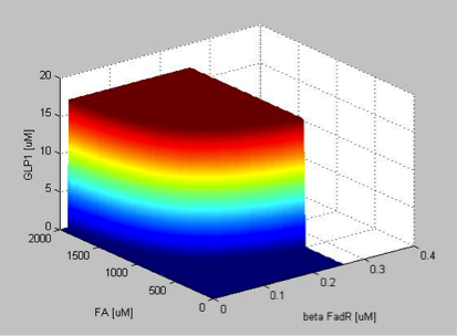
| - | <li style="font-weight : bold; margin-top:20px">beta_FadR</li></html><br />[[File:Team-NTU-Taida-Sys_f8.png|center|350px]]The repression coefficient of FadR describes the concentration of FadR needed to reduce the promoter activity of pFadR to half of its maximum value. Therefore, with higher repression coefficient of FadR, we need more FadR to repress the promoter activity of pFadR, that is, it is more difficult to repress the activity of pFadR. Therefore, TetR1 can be produced at a lower FA concentration, resulting in a lower filter threshold. We can see from the figure that the effect of the repression coefficient of FadR on the threshold is also very dramatic, with opposite trend to that of the repression coefficient of FA. <html> | + | <li style="font-weight : bold; margin-top:20px">beta_FadR</li></html><br />[[File:Team-NTU-Taida-Sys_f8.png|center|350px|thumb|Figure 8]]The repression coefficient of FadR describes the concentration of FadR needed to reduce the promoter activity of pFadR to half of its maximum value. Therefore, with higher repression coefficient of FadR, we need more FadR to repress the promoter activity of pFadR, that is, it is more difficult to repress the activity of pFadR. Therefore, TetR1 can be produced at a lower FA concentration, resulting in a lower filter threshold. We can see from the figure that the effect of the repression coefficient of FadR on the threshold is also very dramatic, with opposite trend to that of the repression coefficient of FA. <html> |
</ol></html> | </ol></html> | ||
| - | ==Threshold of Our High Pass Filter== | + | ==Threshold Adjustment of Our High Pass Filter== |
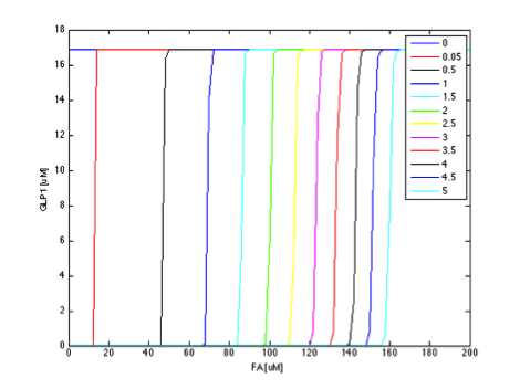
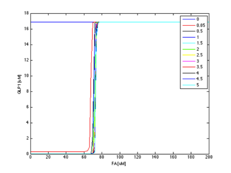
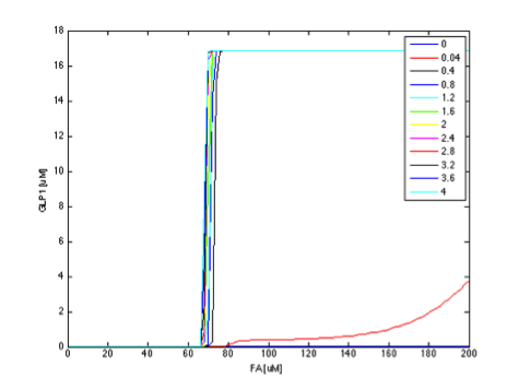
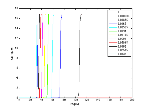
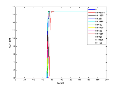
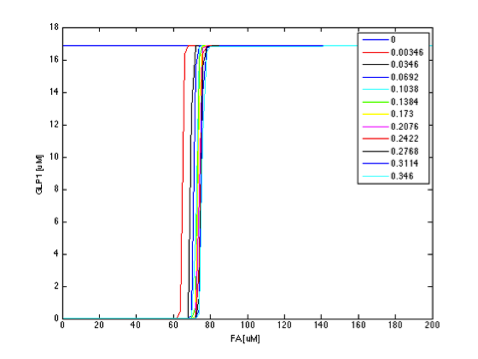
The parameter analysis also gives us insights about how to optimize our circuit response. In our project, we want to create a fatty acid high pass filter with given filter threshold. Therefore, we want to gain better knowledge into the role each parameter plays in determining the overall threshold. From the above results, we can see that adjusting certain parameters results in more significant effect on output response than adjusting other parameters. We further clarify this by plotting the y-z cut planes with different FadR production rate values on the same two-dimensional figure, as shown in figures 9 to 14. In these figures, we have the colored curves represent different parameter values, the x-axis representing the concentration of FA, and the y-axis showing GLP1 concentration. In this manner, it is easy to see how the input-output relation varies with different parameter values. | The parameter analysis also gives us insights about how to optimize our circuit response. In our project, we want to create a fatty acid high pass filter with given filter threshold. Therefore, we want to gain better knowledge into the role each parameter plays in determining the overall threshold. From the above results, we can see that adjusting certain parameters results in more significant effect on output response than adjusting other parameters. We further clarify this by plotting the y-z cut planes with different FadR production rate values on the same two-dimensional figure, as shown in figures 9 to 14. In these figures, we have the colored curves represent different parameter values, the x-axis representing the concentration of FA, and the y-axis showing GLP1 concentration. In this manner, it is easy to see how the input-output relation varies with different parameter values. | ||
| Line 62: | Line 63: | ||
{| align="center" | {| align="center" | ||
| - | | [[File:Team-NTU-Taida-Sys_f9.png|330px|center]] | + | | [[File:Team-NTU-Taida-Sys_f9.png|thumb|330px|center|Figure 9]] |
| - | | [[File:Team-NTU-Taida-Sys_f10.png|330px|center]] | + | | [[File:Team-NTU-Taida-Sys_f10.png|330px|thumb|center|Figure 10]] |
|} | |} | ||
| - | [[File:Team-NTU-Taida-Sys_f11.png|330px|center]] | + | [[File:Team-NTU-Taida-Sys_f11.png|330px|center|thumb|Figure 11]] |
===Protein Degradation Rate=== | ===Protein Degradation Rate=== | ||
{| align="center" | {| align="center" | ||
| - | | [[File:Team-NTU-Taida-Sys_f12.png|330px|center | + | | [[File:Team-NTU-Taida-Sys_f12.png|330px|center|thumb|Figure 12]] |
| - | | | + | | [[File:Team-NTU-Taida-Sys_f13.png|330px|center|thumb|Figure 13]] |
| - | | | + | |
| - | [[File:Team-NTU-Taida- | + | |
| - | + | ||
| - | + | ||
| - | + | ||
| - | | | + | |
| - | + | ||
|} | |} | ||
| + | [[File:Team-NTU-Taida-Sys_f14.png|330px|center|thumb|Figure 14]] | ||
Comparing the above results, we can see that degradation and production rate of FadR have greater effect on the threshold of our circuit. Due to the intrinsic constraints, it is more difficult to vary the degradation rate of proteins. However, we can adjust the production rate of proteins by choosing ribosome binding sites of different strength and by choosing appropriate plasmid copy number. | Comparing the above results, we can see that degradation and production rate of FadR have greater effect on the threshold of our circuit. Due to the intrinsic constraints, it is more difficult to vary the degradation rate of proteins. However, we can adjust the production rate of proteins by choosing ribosome binding sites of different strength and by choosing appropriate plasmid copy number. | ||
Therefore, we chose the production rate of FadR to be the parameter being adjusted and amplified the value from 1 µM/min to 100 µM/min, changing the threshold from 0.1 to 0.8 mM, as shown in Figure 15 and Figure 16. | Therefore, we chose the production rate of FadR to be the parameter being adjusted and amplified the value from 1 µM/min to 100 µM/min, changing the threshold from 0.1 to 0.8 mM, as shown in Figure 15 and Figure 16. | ||
| + | |||
| + | {| align="center" | ||
| + | | [[File:Team-NTU-Taida-Sys_f15.png|330px|center|thumb|Figure 15]] | ||
| + | | [[File:Team-NTU-Taida-Sys_f16.png|330px|center|thumb|Figure 16]] | ||
| + | |} | ||
| + | |||
Latest revision as of 04:03, 27 October 2012
System Analysis
Contents |
Overview
We have found the filter threshold suitable for real physiological condition, which is about 800 uM. Next we have to find the way to adjust the threshold of our circuit to this value. We performed system analysis to find the most suitable parameter to adjust the threshold of our circuit. System analysis explores extensively into the parameter space by sweeping each parameters for certain range while make the others constant. In this way, we can see the corresponding output response when the value of a specific parameter varies within a certain extent. It provides deep insights into the roles each parameter plays in our single cell model. In one aspect, it examines the robustness of our system. In another aspect, it provides valuable information helping us to determine which parameters should be adjusted in order to achieve our expected circuit response, that is, to tune the threshold of our high-pass filter to the desired level. After performing system analysis, we chose the production rate as the parameter to be adjusted. By tuning the value of production rate of FadR from 1 µM/min to 100 µM/min, we changed the threshold from 0.1 to 0.8 mM.
Parameter Sweeping
Our system analysis model is an extension of our single cell model. In order to perform the parameter sweeping, we replace the constant values of parameters with a range of values. For simplicity, we focus only on the steady state of our circuit. The steady states of each species are derived using Maple, and are then ported to Matlab for simulation. The input of our system, the fatty acid, is also included as our sweeping parameters in each sweep, enabling us to observe the threshold of the filter in our circuit. The combined input and parameter sweeping gives us a 3-dimensional graph, with x-axis, y-axis and z-axis being the parameter under analysis, the input fatty acid concentration and the output GLP1 concentration, respectively.
$$X_{FadR}=\frac{\alpha_{FadR}}{\gamma_{FadR}}\times \frac{\beta^{n2}_{FA}}{FA^{n2}+\beta^{n2}_{FA}}$$
$$LuxI_{SS}=\alpha_{aaa}\times\frac{\frac{\beta^{n1}_{FadR}}{\beta^{n1}_{FadR}+X^{n1}_{FadR}}}{\gamma_{aaa}}$$
$$AHL_{e_{SS}}=0$$
$$AHL_{i_{SS}}=\frac{ks1\times LuxI_{SS}+\eta\times AHL_{e_{SS}}}{ks0+\eta}$$
$$LuxR_{SS}=10$$
$$R_{SS}=\rho\times LuxR_{SS}^2\times\frac{AHL_{i_{SS}}^2}{\gamma_R}$$
$$TetR1_{SS}=\alpha_{TetR1}\times\frac{\frac{\beta^{n1}_{FadR}}{\beta^{n1}_{FadR}+X^{n1}_{FadR}}}{\gamma_{TetR1}}$$
$$TetR2_{SS}=\alpha_{TetR2}\times\frac{\frac{\beta^{n3}_{FadR}}{\beta^{n3}_{R}+X^{n3}_{R}}}{\gamma_{TetR2}}$$
$$FadR_{SS}=\frac{\alpha_{FadR}}{\gamma_{FadR}}$$
$$LacI=\frac{\frac{\alpha_LacI}{1+(\frac{TetR1_{SS}+TetR2_{SS}}{\beta_{TetR}})^{n5}}}{\gamma_{LacI}}$$
$$GLP1_{SS}=\frac{\frac{\alpha_{GLP1}}{1+(\frac{LacI_{SS}}{\beta_{LacI}})^{n6}}}{\gamma_{GLP1}}$$
Results
The following figures show the results of the sweeping of protein production rates, repression coefficients and degradation rates.
System Robustness
Protein Production Rate
- alpha_FadR
- alpha_LacI
- alpha_TetR
When the FadR production rate is zero, there is no FadR existing in the cell, and therefore TetR is not repressed, resulting in the expression of GLP1 in high level regardless of the FA concentration. After the FadR production rate goes above a threshold not far from 0, sharp transitions between the maximum level of GLP1 and zero appears, as shown by the rainbow-color, nearly vertical plane. The FA value of the intersection between the vertical plane and the ground horizontal plane is the value of FA that triggers the system to produce GLP1, and therefore can represent the filtering threshold of our circuit. FadR production rate affects the value of the threshold dramatically as can be seen by the shifts of the intersection between the vertical plane and horizontal plane rapidly to higher FA values as the production rate increases. The result can be more clearly seen when plotting the y-z cut plane with different FadR production rate values on the same two-dimensional figure, as shown in Figure 9 in the next section.
When the LacI production rate is zero, there is no LacI present in the cell, which means that GLP-1 is not repressed. So that GLP-1 remains high at this value regardless of FA concentration. After the LacI production rate goes above a threshold very close to 0, sharp transitions between the maximum level of GLP1 and zero appears. We can observe that above the threshold the GLP-1 response is very robust to the change in LacI production rate, maintaining the constant maximum GLP1 level as the LacI production rate varies. LacI production rate has no significant effect on the value of the threshold as can be seen by the almost constant FA value of the intersections between the vertical plane and horizontal plane as the production rate increases. The result can be more clearly seen in the corresponding 2D figure.
When the TetR production rate is zero, there is no TetR present in the cell, so that LacI is not repressed and is free to block the expression of GLP1. Therefore, there are no GLP1 expressed despite of the high FA input. As soon as the production rate becomes non-zero, the production of GLP1 appears abruptly and with sharp threshold. The maximum level of GLP1 expression stays at a constant value with varying TetR production rate, indicating that the expression of GLP1 is able to resist fluctuations in TetR production rate. It can be seen that the threshold of FA filter varies very little with varying TetR production rate, as can be seen by the almost constant FA value of the intersections between the vertical plane and horizontal plane as the TetR production rate increases.
Protein Degradation Rate
- gamma_FadR
- gamma_LacI
- gamma_TetR
If the FadR degradation rate is very low, the concentration of FadR will be higher thus blocking the synthesis of TetR. GLP1 express the maximum expression level at lower FA input concentrations as the FadR degradation rate increases. However, the maximum level of GLP expression is unaffected by the varying FadR degradation rate. When the FadR degradation rate is very high, FadR is degraded almost instantly after it is produced so that FadR is almost absent in the cell. Therefore TetR will not be repressed as long as the concentration of FA exceeds a small level, resulting in a low input threshold.
The degradation rate of LacI follows a similar pattern as the production rate of TetR. If the LacI degradation rate is very low, the concentration of LacI will be higher, directly blocking synthesis of GLP1. The maximum level of GLP1 is not sensitive to variations of LacI degradation rates and neither is the filtering threshold.
If the TetR degradation rate is very low, the concentration of TetR will be higher, thus indirectly facilitating the synthesis of GLP1, as can be seen by the constant high value of GLP1 expression independent of the FA concentration when the degradation rate of TetR is zero. The filtering threshold is not sensitive to variations of the TetR degradation rate.
Repression Coefficient
- beta_FA
- beta_FadR
The repression coefficient of FA describes the concentration of fatty acid needed to reduce the repression activity of FadR to half of its maximum value. Therefore, with higher repression coefficient of FA, we need more fatty acid to enable the expression of TetR1, therefore resulting in a higher filter threshold. We can see from the figure that the effect of the repression coefficient of FA on the threshold is very dramatic.
The repression coefficient of FadR describes the concentration of FadR needed to reduce the promoter activity of pFadR to half of its maximum value. Therefore, with higher repression coefficient of FadR, we need more FadR to repress the promoter activity of pFadR, that is, it is more difficult to repress the activity of pFadR. Therefore, TetR1 can be produced at a lower FA concentration, resulting in a lower filter threshold. We can see from the figure that the effect of the repression coefficient of FadR on the threshold is also very dramatic, with opposite trend to that of the repression coefficient of FA.
Threshold Adjustment of Our High Pass Filter
The parameter analysis also gives us insights about how to optimize our circuit response. In our project, we want to create a fatty acid high pass filter with given filter threshold. Therefore, we want to gain better knowledge into the role each parameter plays in determining the overall threshold. From the above results, we can see that adjusting certain parameters results in more significant effect on output response than adjusting other parameters. We further clarify this by plotting the y-z cut planes with different FadR production rate values on the same two-dimensional figure, as shown in figures 9 to 14. In these figures, we have the colored curves represent different parameter values, the x-axis representing the concentration of FA, and the y-axis showing GLP1 concentration. In this manner, it is easy to see how the input-output relation varies with different parameter values.
If the curves in different color show a rather dense and overlapping distribution, then it means that the value of threshold is rather insensitive to the parameter under test and is less likely to tune the threshold by adjusting the parameter. In contrast, if the curves scattered broadly across the x-axis, then it means the threshold is sensitive to the parameter and it is efficient to tune the threshold by the parameter under test.
In this way, we can find the most efficient way to achieve our desired threshold value, with the least extent of parameters being adjusted. This ensures higher success rate in wet-lab experiment, since a parameter can only be adjusted within a certain range. The results are shown as below,
Protein Production Rate
Protein Degradation Rate
Comparing the above results, we can see that degradation and production rate of FadR have greater effect on the threshold of our circuit. Due to the intrinsic constraints, it is more difficult to vary the degradation rate of proteins. However, we can adjust the production rate of proteins by choosing ribosome binding sites of different strength and by choosing appropriate plasmid copy number.
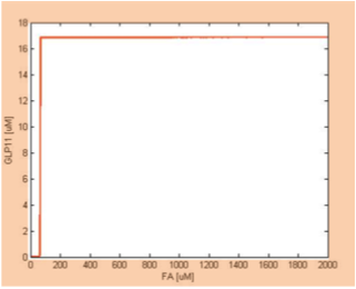
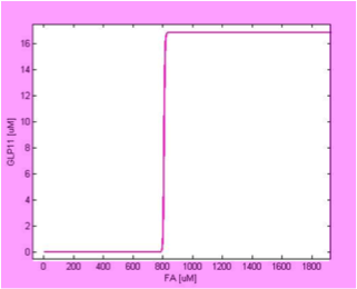
Therefore, we chose the production rate of FadR to be the parameter being adjusted and amplified the value from 1 µM/min to 100 µM/min, changing the threshold from 0.1 to 0.8 mM, as shown in Figure 15 and Figure 16.
 "
"


