Team:Peking/Modeling/Luminesensor/Simulation
From 2012.igem.org
m |
|||
| Line 88: | Line 88: | ||
<div> | <div> | ||
<p class="description"> | <p class="description"> | ||
| - | + | Figure 2. ODE Simulation Result of the prototype Luminesensor. | |
</p> | </p> | ||
</div> | </div> | ||
| Line 96: | Line 96: | ||
</p> | </p> | ||
</div> | </div> | ||
| + | |||
<div class="PKU_context floatR"> | <div class="PKU_context floatR"> | ||
<h3 id="title3">Stochastic Simulation</h3> | <h3 id="title3">Stochastic Simulation</h3> | ||
| Line 105: | Line 106: | ||
<div> | <div> | ||
<p class="description"> | <p class="description"> | ||
| - | + | Figure 3. Stochastic Simulation Result of the prototype Luminesensor. | |
</p> | </p> | ||
</div> | </div> | ||
| Line 112: | Line 113: | ||
According to the figure above, the noise did not influence this system. Thus, the <i>Luminesensor</i> is expected to work theoretically. Besides, the average value of stochastic simulation is coupled with the result of ODE model, which in turn proves the self-consistency of our ODE model. | According to the figure above, the noise did not influence this system. Thus, the <i>Luminesensor</i> is expected to work theoretically. Besides, the average value of stochastic simulation is coupled with the result of ODE model, which in turn proves the self-consistency of our ODE model. | ||
</p> | </p> | ||
| + | </div> | ||
| + | |||
| + | <div class="PKU_context floatR"> | ||
| + | <h3 id="title3">Simulation for GFP expression regulated by <i>Luminesensor</i></h3> | ||
| + | <p> | ||
| + | |||
| + | </p> | ||
| + | <div class="floatC"> | ||
| + | <img src="/wiki/images/9/97/Peking2012_Modeling_Simulation_Time.png" alt="Simulation Result" style="width:600px;"/> | ||
| + | <div> | ||
| + | <p class="description"> | ||
| + | Figure 4. ODE Simulation Result is correspond to the GFP expression data from the experiment, which suggests that our model is effective to present the experiment situation. | ||
| + | </p> | ||
| + | </div> | ||
| + | </div> | ||
</div> | </div> | ||
</html>{{Template:Peking2012_Color_Epilogue}} | </html>{{Template:Peking2012_Color_Epilogue}} | ||
Revision as of 22:13, 25 September 2012
ODE model
According to the previous network and ODE model, we listed all the differential equations and simulated this system with MATLAB with equations listed as
And parameters as
| Parameter | Value | Unit | Description | Source |
| k1 | 3.x10-4 | s-1 | vivid decay rate constant | |
| k2 | 5.6x10⁻⁵ | s-1 | vivid dissociation rate constant | [3] |
| k3 | 8.x10-4 | s-1 | monomer LexA releasing rate constant from specific binding site | |
| k4 | 1.x10-3 | s-1 | binded monomer LexA dissociation rate constant | |
| k5 | 1.x10-4 | s-1 | dimered LexA releasing rate constant from specific binding site | |
| K1(Dark) | 0 | 1 | equilibrium excitation constant on dark | |
| K1(Light) | 1.x10+3 | 1 | equilibrium excitation constant on light | |
| K2 | 7.7x10⁻⁵ | (n mol/L)-1 | vivid association equilibrium constant | [4] |
| K3 | 1.x10-3 | (n mol/L)-1 | monomer LexA binding equilibrium constant with specific binding site | [2] |
| K4 | K2xK5/K3 | (n mol/L)-1 | binded monomer LexA association equilibrium constant | Thermal Principle |
| K5 | 1. | (n mol/L)-1 | dimered LexA binding equilibrium constant | [2] |
| [LG]0 | 1000 | n mol/L | initial concentration of Luminesensor in ground state | |
| [LA]0 | 0 | n mol/L | initial concentration of Luminesensor in active state | |
| [LA2]0 | 0 | n mol/L | initial concentration of dimered Luminesensor | |
| [DL]0 | 100 | n mol/L | initial concentration of free specific binding site on DNA | high-copy plasmid |
| [LGDL]0 | 0 | n mol/L | initial concentration of dimered Luminesensor binded Luminesensor in ground state | |
| [LADL]0 | 0 | n mol/L | initial concentration of dimered Luminesensor binded Luminesensor in active state | |
| [LA2DL]0 | 0 | n mol/L | initial concentration of binded and dimered Luminesensor |
We specifically watched three expressions to understand the mechanism for Luminesensor.
| Expression | Description | Remark |
| rb = 1 - [DL]/[DT] | This indicates the repressing degree. | DT indicates the total specific binding sites, while the DL indicates the free ones among DT. |
| rd = 2[LA2X]/[LT] | This indicates the dimerizing degree. | LT indicates the total Luminesensor molecules, and LA2X indicates all dimered Luminesensor molecules, i.e. LA2 + LA2DL. |
| ra = ( [LAX] + 2[LA2X] ) /[LT] |
This indicates the activating degree. | LAX indicates all monomer Luminesensor molecules, i.e. LA + LADL. |
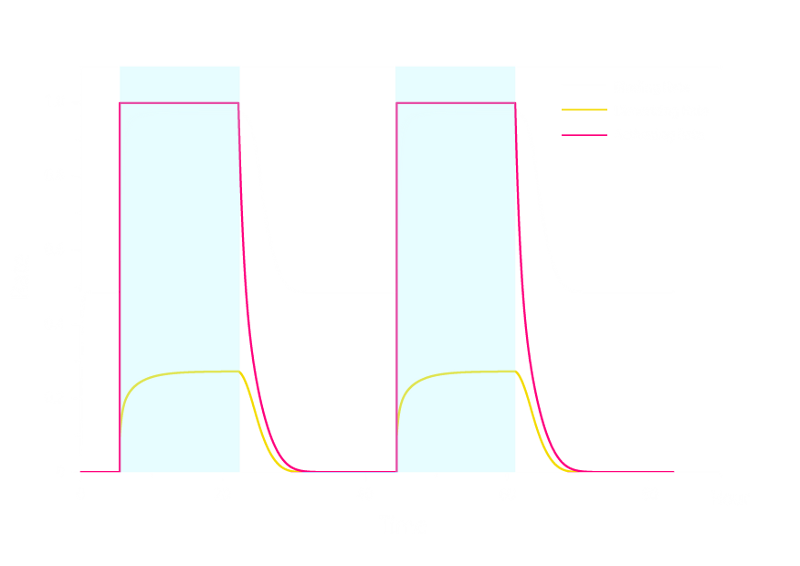
The simulation result is shown below:

Figure 2. ODE Simulation Result of the prototype Luminesensor.
From the figure above, we discovered that the activation and decay of Luminesensor are the pioneers of progress, and the activating rate is the most completely switched variable as lighting varies. The promoter sequences in the DNA are repressed even though the Luminesensor has not all dimered.
Stochastic Simulation
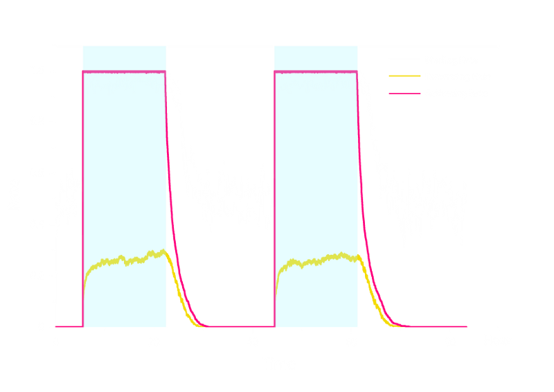
In order to check the working stability of Luminesensor, we simulated this reaction network with a stochastic model. By estimating the volume of a cell, we converted the concentration of a component into the number of molecules by 1 n mol/L : 1. The result are shown below:

Figure 3. Stochastic Simulation Result of the prototype Luminesensor.
According to the figure above, the noise did not influence this system. Thus, the Luminesensor is expected to work theoretically. Besides, the average value of stochastic simulation is coupled with the result of ODE model, which in turn proves the self-consistency of our ODE model.
Simulation for GFP expression regulated by Luminesensor

Figure 4. ODE Simulation Result is correspond to the GFP expression data from the experiment, which suggests that our model is effective to present the experiment situation.
 "
"


