Team:TU-Eindhoven/LEC/Device
From 2012.igem.org
| Line 26: | Line 26: | ||
<p>For the interface between the PC and the device we used two USB-DAQs (Data AcQuisition). Both of them have 4 output channels. By using a matrix configuration for our device we have 16 pixels with these 8 electrodes. These DAQs are then controlled by LabVIEW, in which thus our device software is written. The DAQs can have an output voltage of +10V to -10V with a maximum output of 10mA.</p><br /> | <p>For the interface between the PC and the device we used two USB-DAQs (Data AcQuisition). Both of them have 4 output channels. By using a matrix configuration for our device we have 16 pixels with these 8 electrodes. These DAQs are then controlled by LabVIEW, in which thus our device software is written. The DAQs can have an output voltage of +10V to -10V with a maximum output of 10mA.</p><br /> | ||
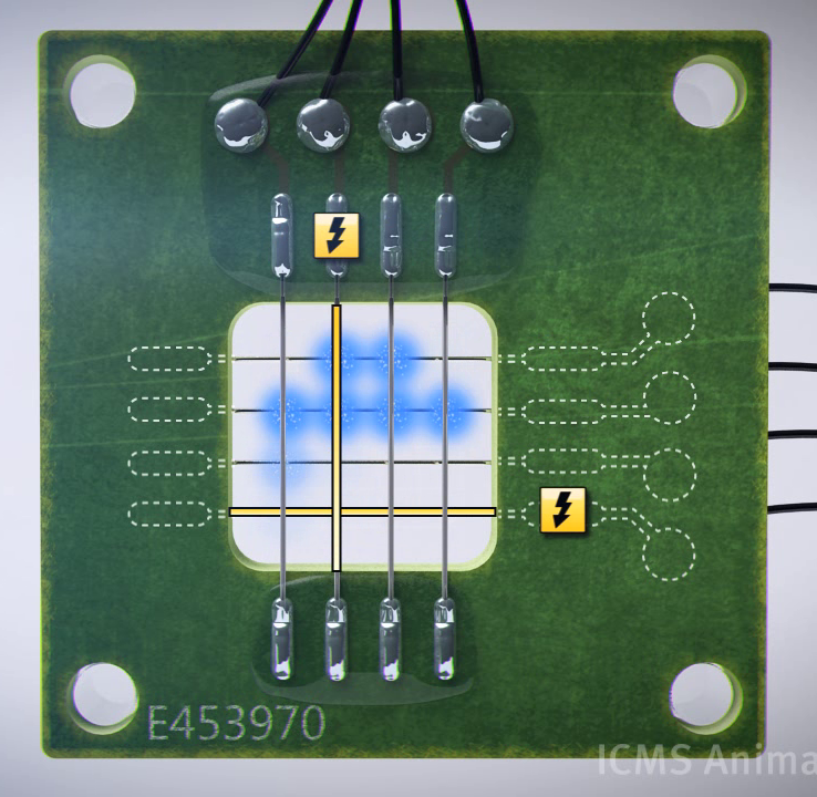
| - | [[File:Device making E.png|300px| | + | [[File:Device making E.png|300px|left|thumb|Snapshot out of the animation displaying how the device creates an image. In this case of the letter 'e'.]]<h3>Software</h3> |
<p>During the development of the software, a few stages are passed. The first version of the software was capable of setting a different voltage to every channel, but this had to be done manually. Although this is enough to test the device in the lab environment, it can’t produce even a single image on the screen.</p> | <p>During the development of the software, a few stages are passed. The first version of the software was capable of setting a different voltage to every channel, but this had to be done manually. Although this is enough to test the device in the lab environment, it can’t produce even a single image on the screen.</p> | ||
Revision as of 12:03, 25 September 2012

The heart of the screen
We have yeast cells that light up when an electric current passes over the membrane. To complete our SOMY-LCD, we also needed something that makes the current on the right places at the right time. For this purpose we created a device with software to provide this control. We will use the yeast in a fluid culture so it can be easily refreshed and in the future the ‘food’ for the yeast can be refilled for long time use of the screen. The fluid culture will consist of a single large medium bath, this causes the resolution to be limited by the device that is used to control the cells only.
Device
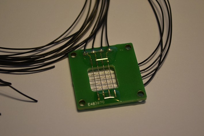
The use of a fluid yeast culture adds some requirements to our device, because now the device not only has to be fully bio-compatible (non-toxic to the yeast), it also has to survive in the harsh conditions of electrolysis in water and high ion concentrations. Therefore we couldn’t use copper for the electrodes. Not only is copper, as a heavy metal, highly toxic to our yeast, the copper would react with the electrolysis releasing the toxic copper ions into the solution and corroding away our electrodes.
Therefore platinum was chosen as the electrode material and we made sure that this was the only metal that came into contact with the medium. All the other metals are covered by either resin or plastic. Because we use the device with living cells we need a way to clean the device properly, therefore all the materials can withstand the temperature of autoclavation and the device can be easily decoupled from the PC to device interface.
For the interface between the PC and the device we used two USB-DAQs (Data AcQuisition). Both of them have 4 output channels. By using a matrix configuration for our device we have 16 pixels with these 8 electrodes. These DAQs are then controlled by LabVIEW, in which thus our device software is written. The DAQs can have an output voltage of +10V to -10V with a maximum output of 10mA.
Software
During the development of the software, a few stages are passed. The first version of the software was capable of setting a different voltage to every channel, but this had to be done manually. Although this is enough to test the device in the lab environment, it can’t produce even a single image on the screen.
The first step to creating an image is to keep a pixel on without constantly providing an electric signal. Thus some sort of periodic signal is needed. We achieved this by implementing a single square wave to one pixel. Now a periodic on/off signal can be given to one pixel, which results in one pixel being constantly ‘on’.
To do this for all pixels, we need 16 square waves (one per pixel). These square waves then are dephased so that only one square wave gives an ‘on’ signal at a time. This allows us to display a single image constantly on our screen. To display multiple images we looked at time. We used the time to select which of the images should be shown and reset the square waves so that they are synchronized with the change of the image so that the device now can produce a moving image.
However this software still has a lot of overhead (inefficient use of CPU time) as we have a square wave for each pixel while only one is in the ‘on’ state at any given time. By using the time again we cut it down to just one square wave. The advantages this brings isn’t measurable with 16 pixels, but a Full HD screen containing 2.073.600 pixels, has to calculate 2.073.599 less square waves due to this small change in the software.
The device in practice
To validate if the software indeed works, we used a voltage meter to test whether the voltage in the software corresponded with the true voltage output. Give or take a few µV this corresponded perfectly. Also when the device was tested on the yeast medium, the process of hydrolysis was clearly visible. When changing certain parameters in the program to simulate an alternating current the hydrolysis disappeared as it should. However due to low concentrations of both yeast cells and GECO protein we were not able to see any light when testing the device with the yeast cells. The device was also to big to fit inside a more sensitive measurement apparatus. Therefore it can be concluded that the device and software work as they are supposed to, but it cannot be validated if the device can really be used to create a screen.
 "
"

