Team:EPF-Lausanne/Bioreactor

From 2012.igem.org

(Difference between revisions)
(Testing)
(Testing)
 
(10 intermediate revisions not shown)
Line 1: Line 1:
 +
{{:Team:EPF-Lausanne/Template/Header|project}}
-
{{:Team:EPF-Lausanne/Template/Header}}
 
 +
=Bioreactor Construction=
-
=Bioreactor construction=
 
 +
For our project, we made a custom illumination device to test different light conditions for LovTAP activation and for use with the melanopsin channel pathway.
-
For our project we made a custom illumination device to test different light conditions for LovTap activation and for use with the melanopsin channel pathway.
+
==Calculations==
-
==Testing and programming the arduino==
+
In [[Team:EPF-Lausanne/References#Strickland_2008|Strickland's 2008]] paper, it's mentioned that they used 8000 mcd LEDs from [http://www.theledlight.com theledlight.com], with 20º viewing angle and 468 nm at 3.4 V. We bought the same sort of LED from [http://www.ledstar.ch/10-Stueck-LowCost-LED-5mm-blau-13000mcd-ultrahell-unsortiert ledstar.ch].
-
The first step was to get the arduino microcontroller up and running, load some simple programs and test out a few circuits on a breadboard.
+
[[Team:EPF-Lausanne/References#Strickland_2008|Strickland et al]] mention also that LovTAP saturates at 20 mW/cm², and our [[Team:EPF-Lausanne/Modeling/Photoactivation|model]] agrees with it.  
 +
[[File:Team-EPF-Lausanne_Test_plate_label.png|Scheme of our test bioreactor.|thumb]]
-
[[File:1345474379479.jpg|frameless]]
+
The viewing angle of our LEDs is 20º, what means a solid angle of 2 π (1 - cos(20)) = 0.378 steradians. According to the definition of candela (yes, I found it in [http://en.wikipedia.org/wiki/Candela Wikipedia]), our 9 cd LEDs should be providing some 40 mW of radiant energy. In order to get 20 mW/cm², we need to spread them over 2 cm². We can then use a [http://www.sigmaaldrich.com/catalog/product/sigma/z707791 24 well plate], with 1.86 cm² per well.
-
==Preparing the components==
+
Now, at what distance from the plates should the LEDs be? If we take the plates with 1.86 cm² the well, or 1.54 cm in diameter, the distance from LED to well bottom should be around 4.4 cm for getting a 20º LED to cover the whole well. The height of the plates is 22 mm, so we can stack two of them: one with the cell cultures and a second one on top with the LEDs inserted in the lid, one per well.
-
We painted the the part holding the LEDs
+
==Testing and Programming the Arduino==
-
to prevent light from one row leaking into another.
+
 +
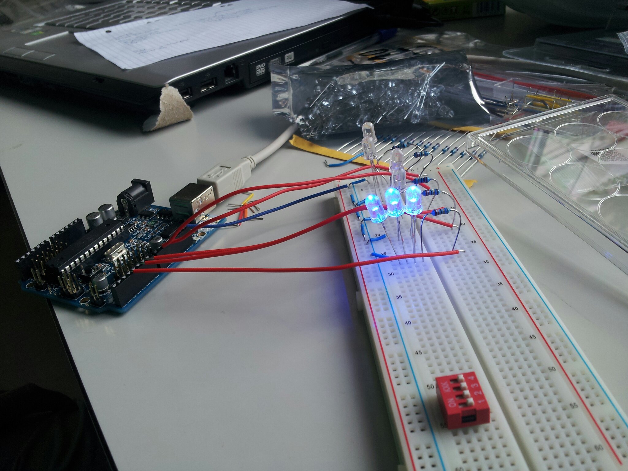
The first step was to get the Arduino microcontroller up and running, load some simple programs and test out a few circuits on a breadboard.
 +
You can find out more about the Arduino open-source electronics prototyping platform and download the Arduino development environment [http://www.arduino.cc/ here].
 +
 +
[[File:1345474379479.jpg|frameless]]
 +
 +
==Preparing the Components==
 +
 +
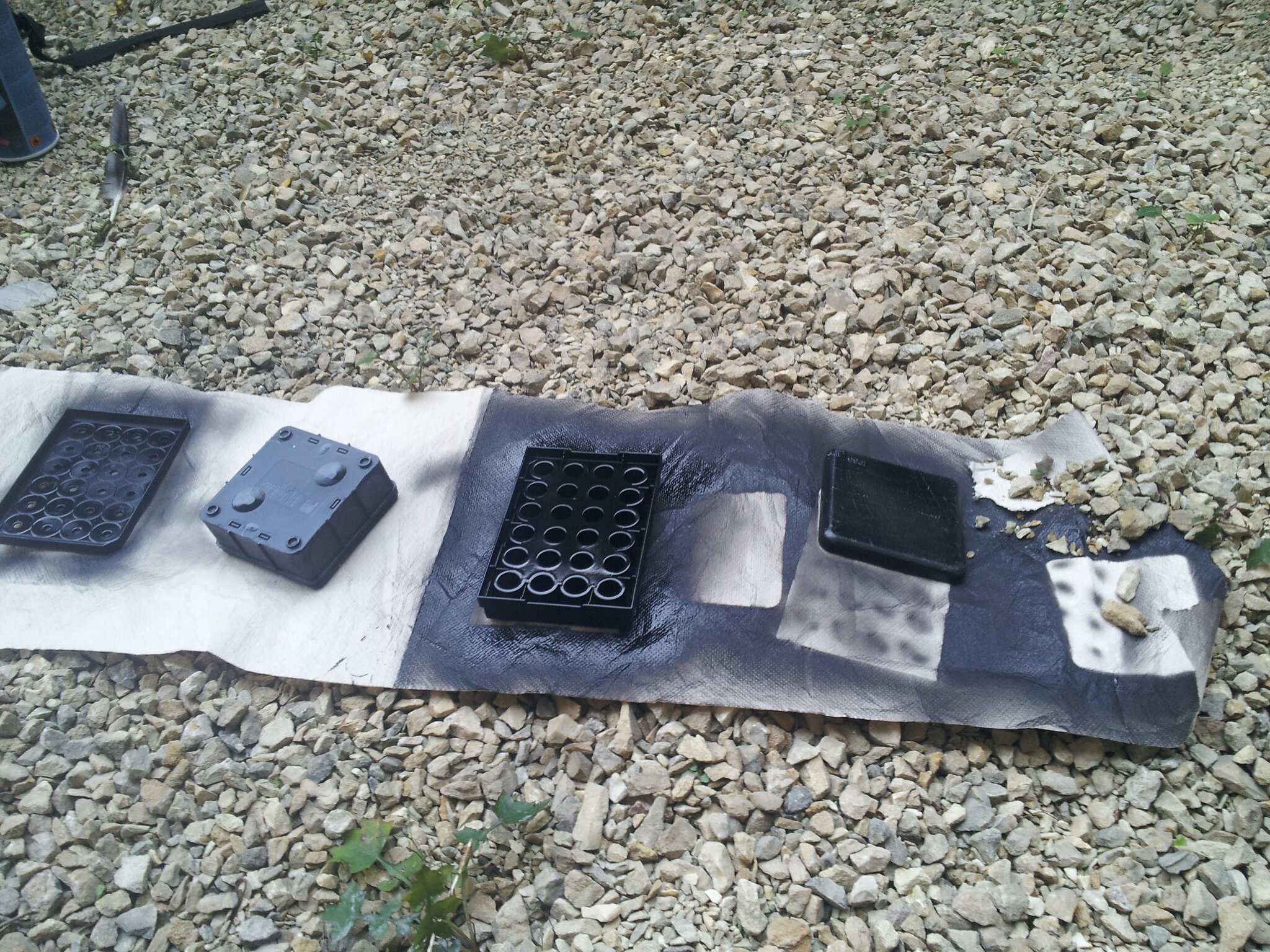
We painted the frame holding the LEDs black
 +
to prevent light from one row leaking into another.
[[File:1346682728902.jpg|frameless]]
[[File:1346682728902.jpg|frameless]]
-
==Soldering and assembly==
+
==Soldering and Assembly==
-
Here we are reating a permanent version of the circuit on a breadboard with some solder.
+
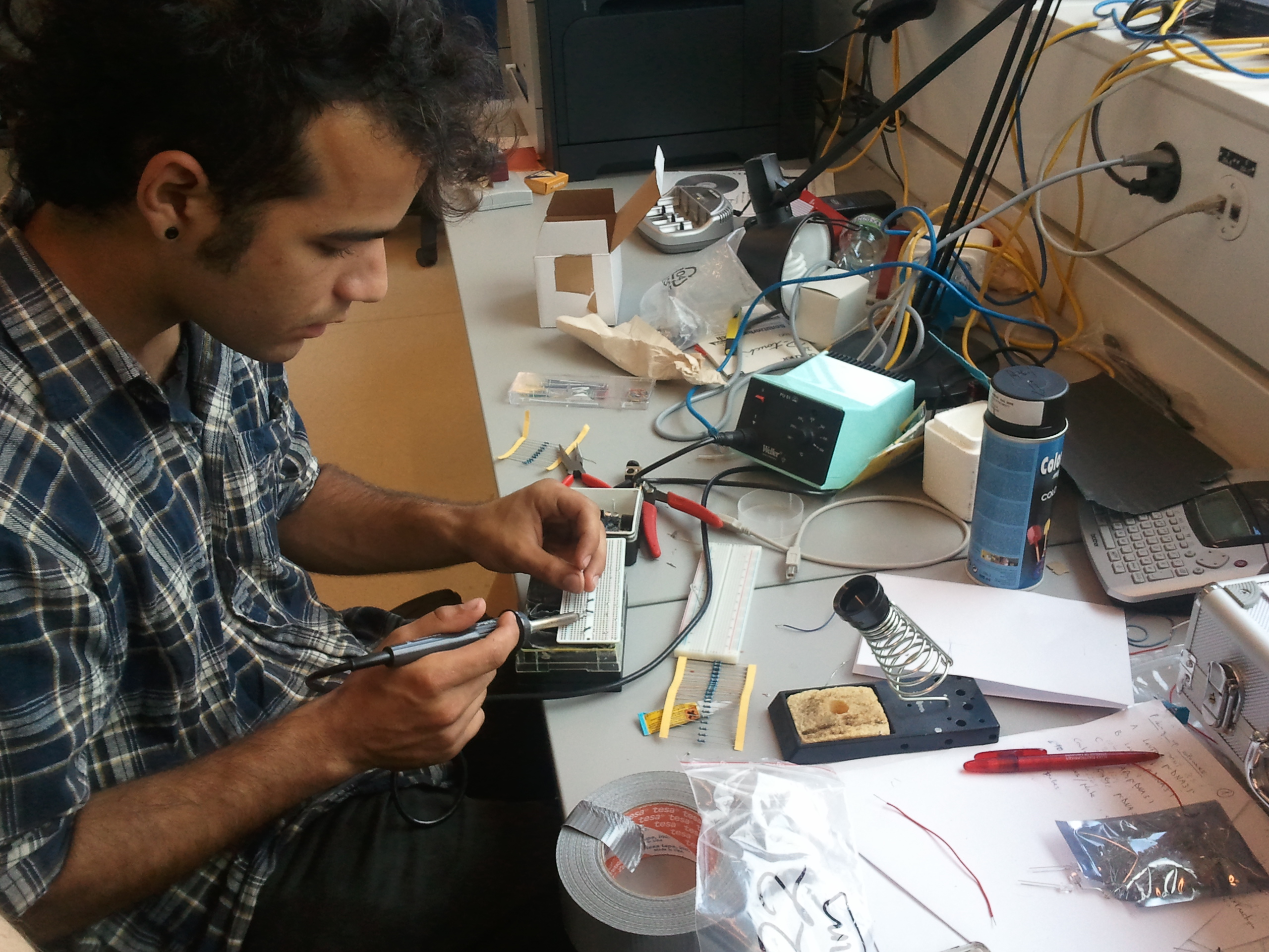
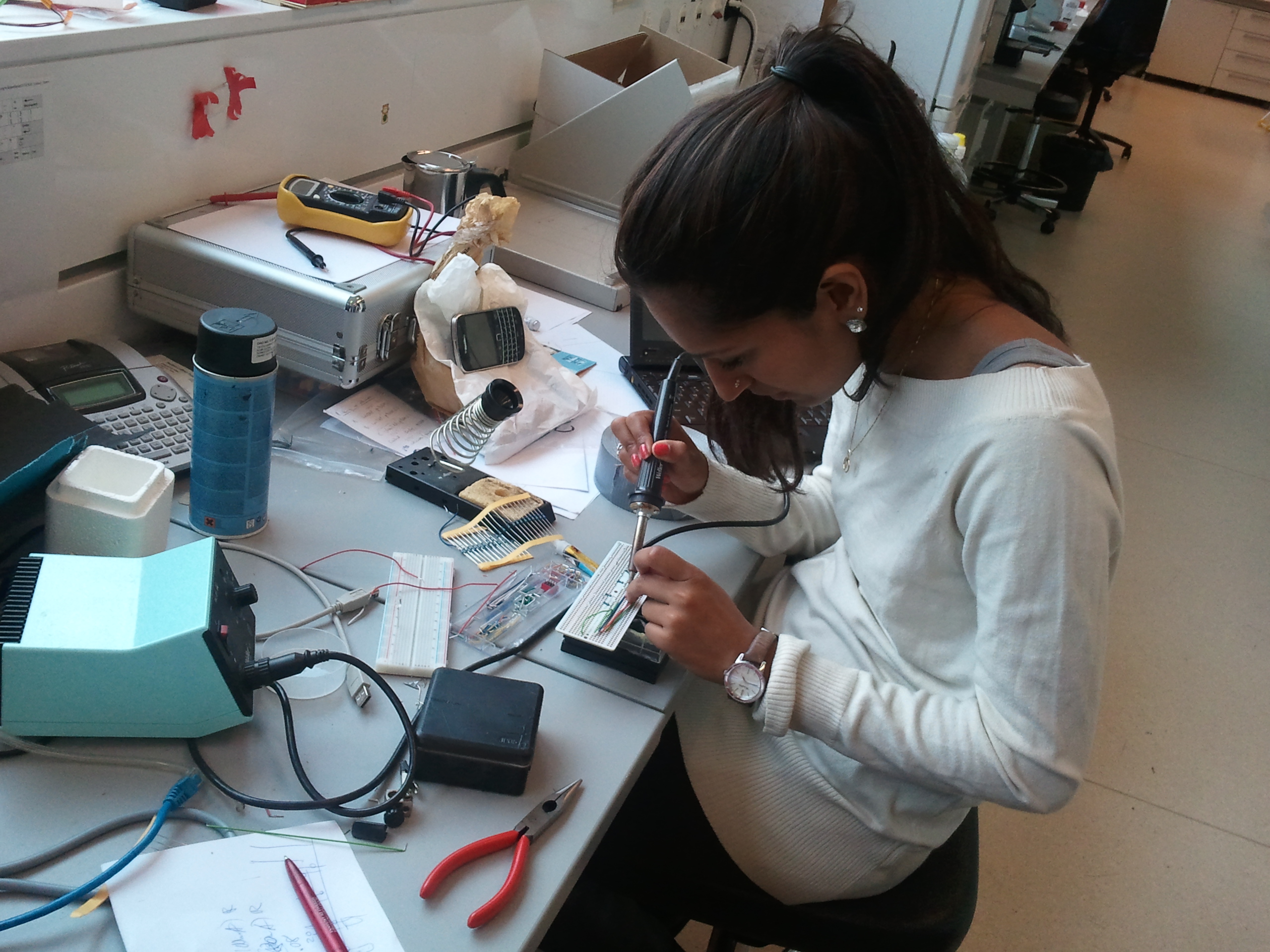
Here we are creating a permanent version of the circuit on a breadboard with some solder.
Line 32: Line 42:
[[File:2012-09-04 16.44.12.jpg|frameless]]
[[File:2012-09-04 16.44.12.jpg|frameless]]
-
And now the arduino is connected to the device.
+
And now the Arduino is connected to the device.
[[File:2012-09-04 18.37.30.jpg|frameless]]
[[File:2012-09-04 18.37.30.jpg|frameless]]
Line 41: Line 51:
[[File:2012-09-04 19.05.07.jpg|frameless]]
[[File:2012-09-04 19.05.07.jpg|frameless]]
 +
 +
This is a video of our device lighting up some LEDs assigned by us with a simple program.
<html>
<html>
-
<iframe width="420" height="315" src="http://www.youtube.com/embed/x3aF_YvoyXc" frameborder="0" allowfullscreen></iframe>
+
<iframe width="560" height="315" src="http://www.youtube.com/embed/tNVq0ltdj9g" frameborder="0" allowfullscreen></iframe>
</html>
</html>
{{:Team:EPF-Lausanne/Template/Footer}}

Latest revision as of 03:22, 27 September 2012


Contents

Bioreactor Construction

For our project, we made a custom illumination device to test different light conditions for LovTAP activation and for use with the melanopsin channel pathway.

Calculations

In Strickland's 2008 paper, it's mentioned that they used 8000 mcd LEDs from [http://www.theledlight.com theledlight.com], with 20º viewing angle and 468 nm at 3.4 V. We bought the same sort of LED from [http://www.ledstar.ch/10-Stueck-LowCost-LED-5mm-blau-13000mcd-ultrahell-unsortiert ledstar.ch].

Strickland et al mention also that LovTAP saturates at 20 mW/cm², and our model agrees with it.

Scheme of our test bioreactor.

The viewing angle of our LEDs is 20º, what means a solid angle of 2 π (1 - cos(20)) = 0.378 steradians. According to the definition of candela (yes, I found it in [http://en.wikipedia.org/wiki/Candela Wikipedia]), our 9 cd LEDs should be providing some 40 mW of radiant energy. In order to get 20 mW/cm², we need to spread them over 2 cm². We can then use a [http://www.sigmaaldrich.com/catalog/product/sigma/z707791 24 well plate], with 1.86 cm² per well.

Now, at what distance from the plates should the LEDs be? If we take the plates with 1.86 cm² the well, or 1.54 cm in diameter, the distance from LED to well bottom should be around 4.4 cm for getting a 20º LED to cover the whole well. The height of the plates is 22 mm, so we can stack two of them: one with the cell cultures and a second one on top with the LEDs inserted in the lid, one per well.

Testing and Programming the Arduino

The first step was to get the Arduino microcontroller up and running, load some simple programs and test out a few circuits on a breadboard. You can find out more about the Arduino open-source electronics prototyping platform and download the Arduino development environment [http://www.arduino.cc/ here].


1345474379479.jpg

Preparing the Components

We painted the frame holding the LEDs black to prevent light from one row leaking into another.

1346682728902.jpg

Soldering and Assembly

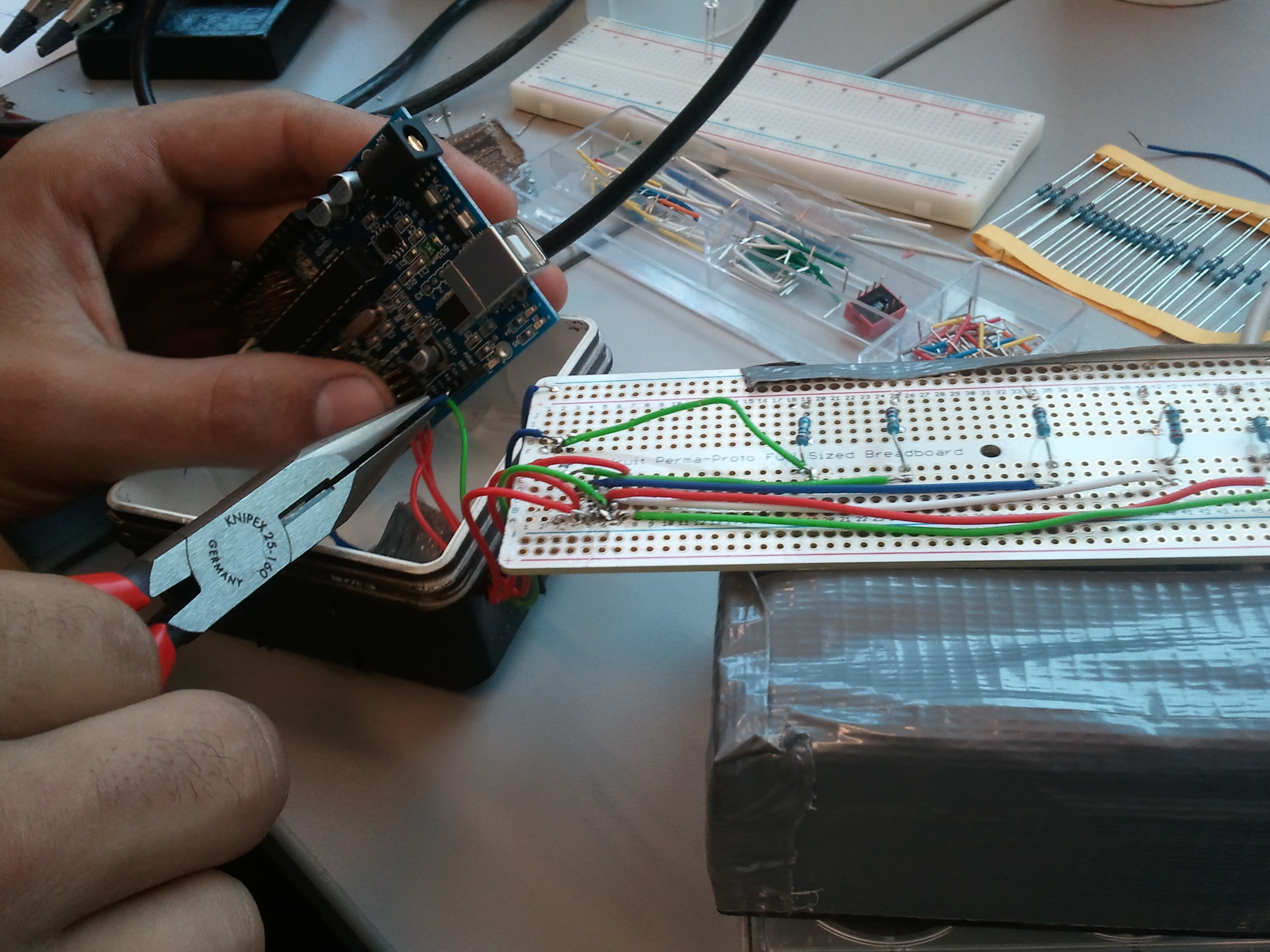
Here we are creating a permanent version of the circuit on a breadboard with some solder.


2012-09-04 15.56.10.jpg 2012-09-04 16.44.12.jpg

And now the Arduino is connected to the device.

2012-09-04 18.37.30.jpg

Testing

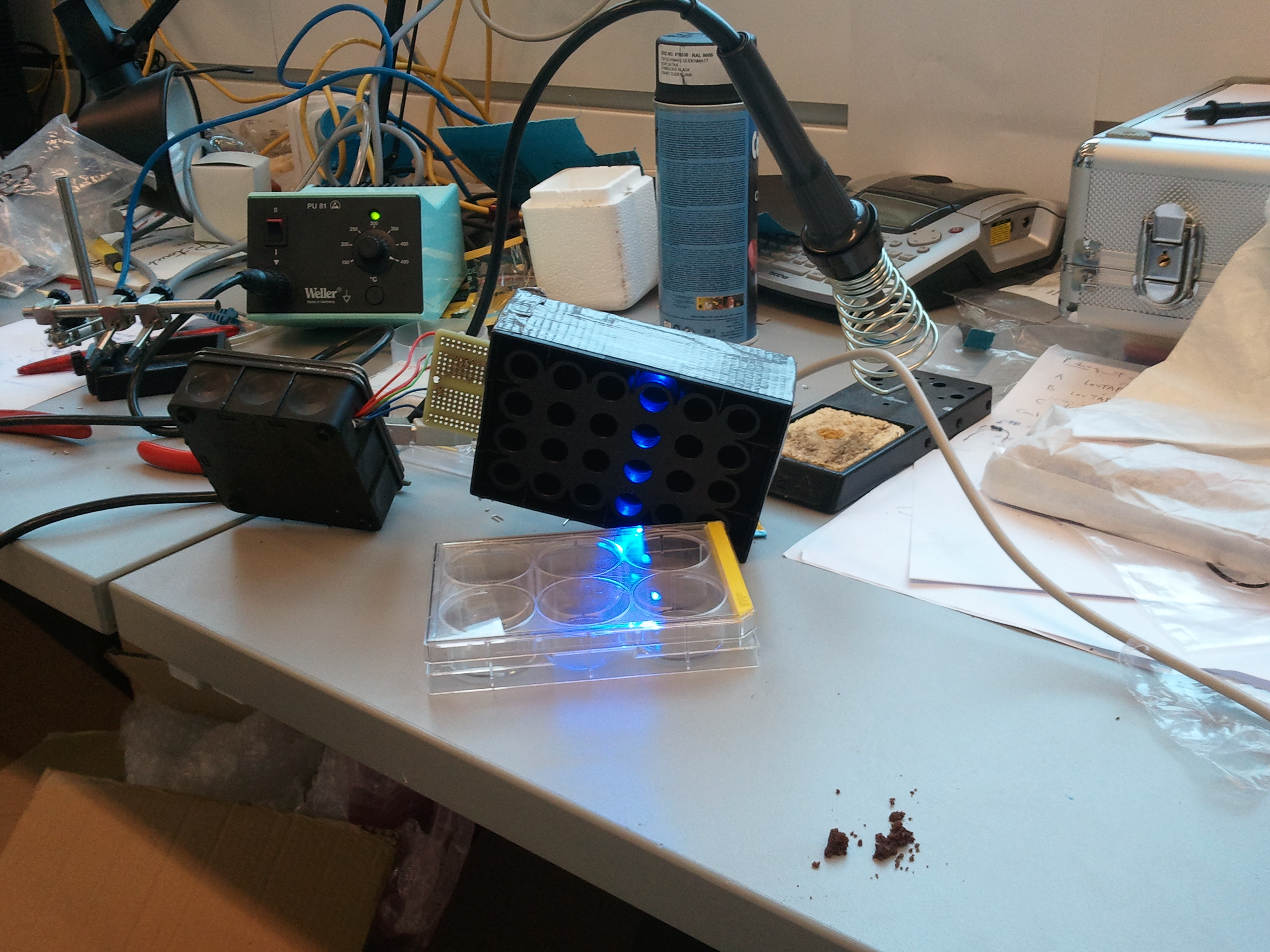
The device works!

2012-09-04 19.05.07.jpg

This is a video of our device lighting up some LEDs assigned by us with a simple program.