Team:Wageningen UR/InsideModification
From 2012.igem.org
(→CCMV with a negative interior) |
(→Methods) |
||
| (273 intermediate revisions not shown) | |||
| Line 1: | Line 1: | ||
{{Template:WUR}} | {{Template:WUR}} | ||
| + | <html><script>document.getElementById("header_slider").style.backgroundImage = "url(https://static.igem.org/mediawiki/2012/6/60/HeaderProject.jpg)";</script></html> | ||
| + | |||
= Inside Modifications = | = Inside Modifications = | ||
| - | + | == Introduction == | |
<p align="justify"> | <p align="justify"> | ||
| - | Since virus-like particles (VLPs) lack genetic content, they enclose an empty space. This space can be filled with proteins such as antibiotics, hormones, and all sorts of pharmaceuticals. Modifications on the inside of the VLPs can increase binding affinity to the loaded substance. The first modifications we pursue is adding the K-coil to the protein subunits at any location that is exposed on the inside of the VLP. In our case, this is a fusion to the N- | + | Since virus-like particles ([[Team:Wageningen_UR/VLPs|VLPs]]) lack genetic content, they enclose an empty space. This space can be filled with proteins such as antibiotics, hormones, and all sorts of pharmaceuticals. Modifications on the inside of the VLPs can increase binding affinity to the loaded substance. The first modifications we pursue is adding the [[Team:Wageningen_UR/Coil_system#E-_and_K-coil|K-coil]] to the protein subunits at any location that is exposed on the inside of the VLP. In our case, this is either a fusion to the N-terminus or to the C-terminus. The coils will facilitate strong attachment to the substance which has to carry the opposite coil. |
| - | The second modification we aim to make is a change in the interior's charge, which is another way to open up more options for loading our VLPs. Normally, the interior of a VLP is positively charged, facilitating interaction with negatively charged DNA/RNA molecules. By changing the amino acid sequence that is located on the interior of a VLP, the positive charge can be changed into a negative charge. A VLP with a negatively charged interior can be loaded with all sorts of positively charged molecules, such as polymeres, | + | The second modification we aim to make is a change in the interior's charge, which is another way to open up more options for loading our VLPs. Normally, the interior of a VLP is positively charged, facilitating interaction with negatively charged DNA/RNA molecules. By changing the amino acid sequence that is located on the interior of a VLP, the positive charge can be changed into a negative charge. A VLP with a negatively charged interior can be loaded with all sorts of positively charged molecules, such as polymeres, metal ions, etc. |
<br><br> | <br><br> | ||
| - | ''' | + | ===Our aims:=== |
| + | <center> | ||
| + | {|border="0" | ||
| + | |- | ||
| + | |1. Construct a VLP that has K-coils exposed on the interior || 2. Construct a VLP that has a negatively charged interior | ||
| + | |- | ||
| + | | [[File:K-coil attached to HepB C-terminal.png|340px|left|thumb|''Figure 1: K-coil on the inside of a Hepatitis B VLP to package molecules specifically using the [https://2012.igem.org/Team:Wageningen_UR/Coil_system Plug and Apply system]'']] || [[File:CCMV_neg_iron_oxide_nanoparticle.png|750px|center|thumb|''Figure 2: A VLP with a negatively charged interior can be loaded with metal ions. This figure shows a schematic overview of a nanoparticle composed of metal ions that is spatially located within a VLP.'']] | ||
| + | |} | ||
| + | </center> | ||
| + | |||
| + | ==CCMV wt with a K-coil on the inside== | ||
| + | The Cowpea Chlorotic Mottle Virus ([[Team:Wageningen_UR/ModifyingtheCCMV|CCMV]]) VLP is one of the best candidates for drug delivery, since it is tolerant of high temperatures and stable at a certain pH range. Next to that, the wild-type CCMV VLP is not specific for mammalian cells in vivo. Because of the promising properties of the CCMV VLPs, we decided to place coiled-coils on the interior. Since the N-terminus of the CCMV coat protein is folded to the inside of the VLP, this was the logic place to attach the coil. Attachment of coiled-coils allows the fusion of a range of molecules, which are immobilized on the inside of the VLP [1]. | ||
<br><br> | <br><br> | ||
| - | + | </p> | |
| + | ===Methods=== | ||
| + | <p align="justify"> | ||
| + | <br> | ||
| + | The attachment of the K-coil to the N-terminus of the CCMV wild-type VLP subunits was carried out in 4 subsequent PCR steps (see figure 3). To ensure the quaternary structure stability of both the CCMV wt capsid protein and the K-coil we placed a flexible linker between them. The flexible linker has following amino acid sequence LGGGGSGGGGSAAA and is reported to be separating two different protein domains effectively [2]. | ||
| + | Unluckily, the primer of the first step was not designed correctly, resulting in a frameshift over the entire VLP, making this construct useless. We discovered this on the 18th of September, when receiving the sequencing results of a similar experiment the attachment of the [[Team:Wageningen_UR/Coil_system|Plug and Apply System]] to the outside of the CCMV Δ25 mutant. | ||
<br><br> | <br><br> | ||
| - | + | [[File:3 step PCR scheme CCMV wt version 2.jpg|700px|center|thumb|''Figure 3: PCR procedure CCMV wt + K-coil'']] | |
<br><br> | <br><br> | ||
| - | |||
| - | |||
</p> | </p> | ||
| - | === | + | ===Results=== |
| - | + | The first two steps of the PCR reactions went well (see figure 4 and 5). Except for the negative positive control of the first PCR step due to a pipetting mistake. We did the second PCR step with the PCR product of sample I (reasonably pure). The third and fourth PCR step of the experiment were redundant because of the wrong primer design in step I. | |
| - | The | + | |
<br><br> | <br><br> | ||
| - | + | [[File:CCMV wt K-coil PCR step1.jpg|400px|left|thumb|''Figure 4: PCR step I CCMV wt + K-coil'']][[File:PCR step II CCMV wt K-coil.jpg|400px|left|thumb|''Figure 5: PCR step II CCMV wt + K-coil'']] | |
| - | ''' | + | <br><br><br><br><br><br><br><br><br><br><br><br><br><br><br><br> |
| - | + | As mentioned before a mistake in primer design caused a serious frameshift resulting in a totally wrong translated protein (see figure 6) | |
| - | <br> | + | |
| - | + | ||
| - | + | ||
<br><br> | <br><br> | ||
| - | [[File: | + | [[File:Frameshift.JPG|700px|center|thumb|''Figure 6: frameshift translation'']] |
| - | + | ||
<br><br> | <br><br> | ||
| - | ''' | + | Figure 7 shows the actual protein translation we wanted to achieve. The mistake was introduced in the ''annealing part'' of the first primer: FW1 FL-CCMV wt 5' TGGTGGTGGTTCTGGTGGTGGTGGTTCTGCTGCTGCT'''''CC'''ATGGGTACAGTCGGAAC'' 3'. These two marked basepairs, initially belonging to the wt CCMV sequence, should have been deleted in our selfmade fusion-protein because they are right in front of the START-codon (ATG). |
| - | + | ||
| - | + | ||
| - | + | ||
<br><br> | <br><br> | ||
| - | + | [[File:Right frame.jpg|700px|center|thumb|''Figure 7: right protein translation CCMV wt K-coil construct'']] | |
<br><br> | <br><br> | ||
| - | + | After the European Jamboree we designed a new FW1 FL-CCMV wt primer: 5' TGGTGGTGGTTCTGGTGGTGGTGGTTCTGCTGCTGCTATGGGTACAGTCGGAACAGG 3'. A new frameshift is avoided by using [http://partsregistry.org/Part:BBa_K883000 BBa_K883000] as a template for the new primer and by checking the translation of the whole construct with the Expasy online translation tool. This [http://partsregistry.org/Part:BBa_K883000 BBa_K883000] has a confirmed sequence and works properly to produce VLPs. With the new primer we are able to repeat our PCR-extension scheme to successfully add the K-coil to the N-terminus of the CCMV wt coat protein. As visible in fig. 8 all 4 PCR steps have been working out (CCMV wt PCR 3 is barely visible though) but unfortunately we were not able to clone the new construct into ''E.coli'' until now. | |
| - | [[ | + | |
| - | + | ||
<br><br> | <br><br> | ||
| + | [[File:Frameshift correction all PCR.jpg|500px|center|thumb|''Figure 8: All four PCR-products of the extension-PCR scheme, the different steps are indicated by roman numbers.'']] | ||
| - | + | ==CCMV with a negative interior== | |
| - | < | + | <p align="justify"> |
| - | + | One of the modifications that was performed on the CCMV VLP was to give the interior a negative charge (See figure 9). Since the N-terminus of each of the 180 CCMV subunits is folded to the inside of the VLP, changing its charge would alter the overall charge of the VLPs interior dramatically. While the wild-type CCMV VLP can not be loaded with positively charged substances, this modified version can [3]. One very interesting feature of these modified VLPs is that they can be loaded with positively charged metal ions. Addition of iron ions to a solution containing these modified VLPs at a pH of 6.5 results in oxidative hydrolysis of the iron on the inside of the VLPs, creating paramagnetic iron oxide nanoparticles [3]. | |
| - | <br><br> | + | <br><br></p> |
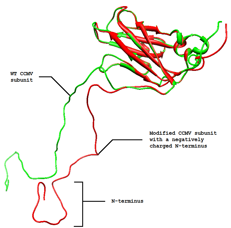
| + | [[File:CCMV_NEG_with_CCMV_WT.PNG|500px|center|thumb|''Figure 9: Phyre2 protein folding prediction of the wild-type CCMV coat protein (green) combined with the desired CCMV coat protein with a negative N-terminus (red). The models have been aligned using the program Chimera 1.6.2. As can be seen, the modified version of the CCMV subunit shows to fold in nearly the same confirmation as the wild-type subunit. This is because the modification is present at the N-terminus which hardly interacts with the body of the protein. '']] | ||
| - | + | ===Methods=== | |
| + | Constructing a CCMV VLP with a negative charge on the interior was facilitated by 3 subsequent PCR steps (figure 10), which replaced 6 Arginine and 3 Lysine residues at the N-Terminus with Glutamic acid residues. As initial template, the CCMV Delta25 mutant was used. This mutant is similar to wt CCMV, but it lacks 25 amino acids at the N-terminus. Luckily, the construct was finished in august and we were able to place an IPTG induced promoter combined with an RBS site in front of it. [https://2012.igem.org/Team:Wageningen_UR/Journal/week17#Lab_work See labjournal]. | ||
<br><br> | <br><br> | ||
| - | + | [[File:Making_of_CCMV_NEG2correct.PNG|600px|center|thumb|<p align="justify">''Figure 10: Three subsequent PCR steps were performed to add a negatively charged N-terminus to the CCMV Delta25 mutant.''</p>]] | |
| - | ''' | + | |
| - | < | + | |
| - | + | ||
<br><br> | <br><br> | ||
| - | [[ | + | ===Results=== |
| + | The next step was to produce VLPs with this new construct, which succeeded. The created biobricks are named [http://partsregistry.org/Part:BBa_K883160 BBa_K883160] & [http://partsregistry.org/Part:BBa_K883161 BBa_K883161]. VLPs were produced using BBa_K883161, which was at that moment present in the pSB1AK3 backbone in JM 109 cells. Protocols for growing the culture, dialysis of the VLPs and purifying the VLPs can be found [https://2012.igem.org/Team:Wageningen_UR/Protocol#CCMV_Coat_Protein_VLP_formation here]. Verification of VLP formation was done by Electron Microscopy (figure 11). In figure 12 a highly magnified image is shown of such a VLP with a negatively charged interior. As a proof of concept, the CCMV VLPs with a negatively charged interior were loaded with iron ions and monitored using electron microscopy. Unluckily, the samples were highly contaminated, which made it impossible to pinpoint any present VLPs. This contamination was possibly caused by the addition of iron to the samples. In figure 13 an image is shown of such a sample in which there is lots of contamination. | ||
<br><br> | <br><br> | ||
| + | [[File:KeesvanderArkontheEM.PNG|350px|left|thumb|<p align="justify">''Figure 11: Visualizing the VLPs using Electron Microscopy''</p>]] | ||
| + | [[File:CCMV_NEG_VLP.png|400px|left|thumb|<p align="justify">''Figure 12: Electron Microscopy image of a CCMV VLP with negative interior. Picture was taken on the 28th of August. Magnification: 40.000''</p>]] | ||
| + | [[File:VLP's_with_iron2.png|300px|left|thumb|<p align="justify">''Figure 13: Electron Microscopy image with lots of contamination, possibly caused by the addition of iron. The structure shown here was repeatedly present all over the sample. Picture was taken on the 24th of September. magnification: 20.000''</p>]] | ||
| + | <br><br><br><br><br><br><br><br><br><br><br><br><br><br><br><br><br><br><br><br><br><br><br><br> | ||
| + | == Hepatitis B with a K-coil on the inside == | ||
| + | [[File:K-coil attached to HepB C-terminal.png|500px|left|thumb|''Figure 14: Estimated position of a core protein fused to a K coil (pink) overlaid on top of the wild type protein (blue) in the Hepatitis B capsule'']] | ||
| - | |||
| - | |||
| - | |||
| - | |||
| - | |||
<p align="justify"> | <p align="justify"> | ||
| + | Deletions as well as modifications to the C-terminal of the Hepatitis B ([https://2012.igem.org/Team:Wageningen_UR/ModifyingtheHepatitisB HepB]) core protein are possible since this part of the protein is not important for VLP formation [4]. Knowing this we can assume that the fusion of a K-coil to the C-terminal will lead to the formation of a VLP with a coil presented on the inside (figure 14). | ||
| + | <br> | ||
| + | <br> | ||
| + | To obtain the maximal amount of space in the VLP capsule we decided to delete a part of the C-terminal that is normally used for DNA binding and not required for VLP folding. After looking at protein folding predictions it was decided to add a short flexible linker between coil and core protein instead (see [https://2012.igem.org/Team:Wageningen_UR/Modeling#Hepatitis_B_inside_modification In silico folding prediction]). | ||
| + | <br><br><br><br><br><br><br><br><br><br><br><br> | ||
| + | </p> | ||
| + | ===Methods=== | ||
| - | + | This modification was carried out in 4 PCR steps extending our construct one step at a time (see figures 15-17). | |
| - | [[File: | + | [[File:LegendePCR steps.png|600px|center|thumb|''Figure 15: Legend'']] |
| - | + | [[File:PrimersPCRHepBinside.png|600px|center|thumb|''Figure 16: Primers for the 4 PCR reactions'']] | |
| - | '' | + | [[File:PCRsteps HepBinside.png|600px|center|thumb|''Figure 17: PCR steps to obtain the fusion of linker and coil'']] |
| - | |||
| - | [[File: | + | [[File:PCR 2nd,3rd step hepinsidecoil.png|250px|left|thumb|Figure 18: 2nd and 3rd step of the HepB inside modification PCR reaction]][[File:4th step PCR hepinsidecoil.png|500px|left|thumb|''Figure 19: Final step of the PCR reactions - the gel shows fragments with the expected size]] |
| - | + | ===Results=== | |
| - | + | After some problems with the last step of the PCR reaction a product with the correct length was obtained (see journal [https://2012.igem.org/Team:Wageningen_UR/Journal/week18 week 18]). Unfortunately the ligation into a vector and transformation with ''E. coli'' did not succeed yet. | |
| - | + | <br><br><br><br><br><br><br><br><br><br><br><br> | |
| - | + | ||
| - | + | ||
| - | + | ||
| - | + | ||
| - | After some problems with the last step of the PCR reaction a product with the correct length was obtained (see journal [https://2012.igem.org/Team:Wageningen_UR/Journal/week18 | + | |
| - | + | ||
| - | + | ||
| - | + | ||
| - | < | + | |
= References = | = References = | ||
| - | 1 | + | 1. Minten, I.J., et al., Controlled encapsulation of multiple proteins in virus capsids. J Am Chem Soc, 2009. 131(49): p. 17771-3. |
| - | + | <br><br> | |
| - | + | 2. Arai, R., H. Ueda, et al. (2001). "Design of the linkers which effectively separate domains of a bifunctional fusion protein." Protein Eng 14(8): 529-532. | |
| - | + | <br><br> | |
3. Douglas, T., et al., Protein Engineering of a Viral Cage for Constrained Nanomaterials Synthesis. Adv. Mater., 2002. 14, No. 6. March 18. p. 415-18. | 3. Douglas, T., et al., Protein Engineering of a Viral Cage for Constrained Nanomaterials Synthesis. Adv. Mater., 2002. 14, No. 6. March 18. p. 415-18. | ||
| + | <br><br> | ||
| + | 4. Beterams, G., Böttcher B., & Nassal M. (15. Sept 2000). Packaging of up to 240 subunits of a 17 kDa nuclease into the interior of recombinant hepatitis B virus capsids. FEBS Lett., S. 169-76. | ||
| + | <br><br> | ||
| + | |||
| + | <html> | ||
| + | <div class="prNav"> | ||
| + | <div class="prev"> | ||
| + | <a href="https://2012.igem.org/Team:Wageningen_UR/OutsideModification#Outside_Modification" title="Outside Modifications">4. Outside Modifications</a> | ||
| + | </div> | ||
| + | <div class="next"> | ||
| + | <a href="https://2012.igem.org/Team:Wageningen_UR/MethodsDetection#Detection_of_Virus_Like_Particles" title="Detection">6. Detection</a> | ||
| + | </div> | ||
| + | </div> | ||
| + | </html> | ||
Latest revision as of 20:52, 26 October 2012
Contents |
Inside Modifications
Introduction
Since virus-like particles (VLPs) lack genetic content, they enclose an empty space. This space can be filled with proteins such as antibiotics, hormones, and all sorts of pharmaceuticals. Modifications on the inside of the VLPs can increase binding affinity to the loaded substance. The first modifications we pursue is adding the K-coil to the protein subunits at any location that is exposed on the inside of the VLP. In our case, this is either a fusion to the N-terminus or to the C-terminus. The coils will facilitate strong attachment to the substance which has to carry the opposite coil.
The second modification we aim to make is a change in the interior's charge, which is another way to open up more options for loading our VLPs. Normally, the interior of a VLP is positively charged, facilitating interaction with negatively charged DNA/RNA molecules. By changing the amino acid sequence that is located on the interior of a VLP, the positive charge can be changed into a negative charge. A VLP with a negatively charged interior can be loaded with all sorts of positively charged molecules, such as polymeres, metal ions, etc.
Our aims:
| 1. Construct a VLP that has K-coils exposed on the interior | 2. Construct a VLP that has a negatively charged interior |
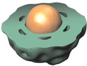
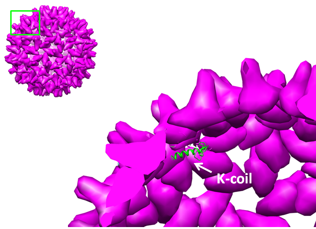 Figure 1: K-coil on the inside of a Hepatitis B VLP to package molecules specifically using the Plug and Apply system |
CCMV wt with a K-coil on the inside
The Cowpea Chlorotic Mottle Virus (CCMV) VLP is one of the best candidates for drug delivery, since it is tolerant of high temperatures and stable at a certain pH range. Next to that, the wild-type CCMV VLP is not specific for mammalian cells in vivo. Because of the promising properties of the CCMV VLPs, we decided to place coiled-coils on the interior. Since the N-terminus of the CCMV coat protein is folded to the inside of the VLP, this was the logic place to attach the coil. Attachment of coiled-coils allows the fusion of a range of molecules, which are immobilized on the inside of the VLP [1].
Methods
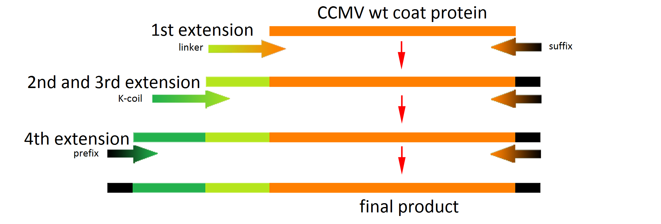
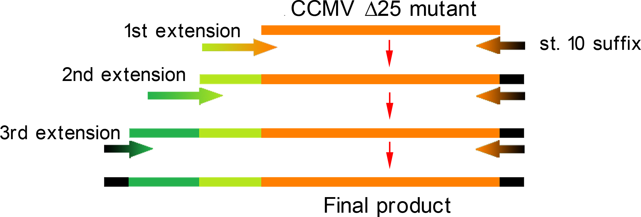
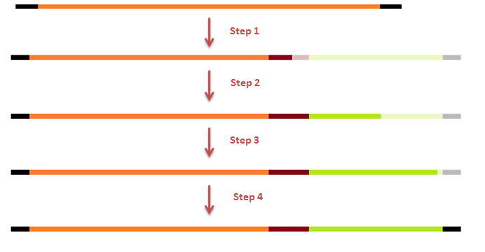
The attachment of the K-coil to the N-terminus of the CCMV wild-type VLP subunits was carried out in 4 subsequent PCR steps (see figure 3). To ensure the quaternary structure stability of both the CCMV wt capsid protein and the K-coil we placed a flexible linker between them. The flexible linker has following amino acid sequence LGGGGSGGGGSAAA and is reported to be separating two different protein domains effectively [2].
Unluckily, the primer of the first step was not designed correctly, resulting in a frameshift over the entire VLP, making this construct useless. We discovered this on the 18th of September, when receiving the sequencing results of a similar experiment the attachment of the Plug and Apply System to the outside of the CCMV Δ25 mutant.
Results
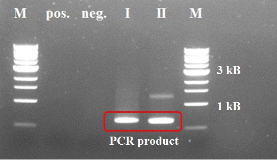
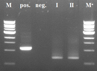
The first two steps of the PCR reactions went well (see figure 4 and 5). Except for the negative positive control of the first PCR step due to a pipetting mistake. We did the second PCR step with the PCR product of sample I (reasonably pure). The third and fourth PCR step of the experiment were redundant because of the wrong primer design in step I.
As mentioned before a mistake in primer design caused a serious frameshift resulting in a totally wrong translated protein (see figure 6)
Figure 7 shows the actual protein translation we wanted to achieve. The mistake was introduced in the annealing part of the first primer: FW1 FL-CCMV wt 5' TGGTGGTGGTTCTGGTGGTGGTGGTTCTGCTGCTGCTCCATGGGTACAGTCGGAAC 3'. These two marked basepairs, initially belonging to the wt CCMV sequence, should have been deleted in our selfmade fusion-protein because they are right in front of the START-codon (ATG).
After the European Jamboree we designed a new FW1 FL-CCMV wt primer: 5' TGGTGGTGGTTCTGGTGGTGGTGGTTCTGCTGCTGCTATGGGTACAGTCGGAACAGG 3'. A new frameshift is avoided by using [http://partsregistry.org/Part:BBa_K883000 BBa_K883000] as a template for the new primer and by checking the translation of the whole construct with the Expasy online translation tool. This [http://partsregistry.org/Part:BBa_K883000 BBa_K883000] has a confirmed sequence and works properly to produce VLPs. With the new primer we are able to repeat our PCR-extension scheme to successfully add the K-coil to the N-terminus of the CCMV wt coat protein. As visible in fig. 8 all 4 PCR steps have been working out (CCMV wt PCR 3 is barely visible though) but unfortunately we were not able to clone the new construct into E.coli until now.
CCMV with a negative interior
One of the modifications that was performed on the CCMV VLP was to give the interior a negative charge (See figure 9). Since the N-terminus of each of the 180 CCMV subunits is folded to the inside of the VLP, changing its charge would alter the overall charge of the VLPs interior dramatically. While the wild-type CCMV VLP can not be loaded with positively charged substances, this modified version can [3]. One very interesting feature of these modified VLPs is that they can be loaded with positively charged metal ions. Addition of iron ions to a solution containing these modified VLPs at a pH of 6.5 results in oxidative hydrolysis of the iron on the inside of the VLPs, creating paramagnetic iron oxide nanoparticles [3].
Methods
Constructing a CCMV VLP with a negative charge on the interior was facilitated by 3 subsequent PCR steps (figure 10), which replaced 6 Arginine and 3 Lysine residues at the N-Terminus with Glutamic acid residues. As initial template, the CCMV Delta25 mutant was used. This mutant is similar to wt CCMV, but it lacks 25 amino acids at the N-terminus. Luckily, the construct was finished in august and we were able to place an IPTG induced promoter combined with an RBS site in front of it. See labjournal.
Results
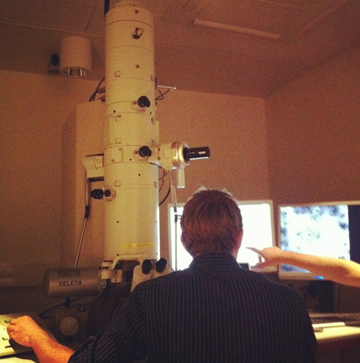
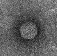
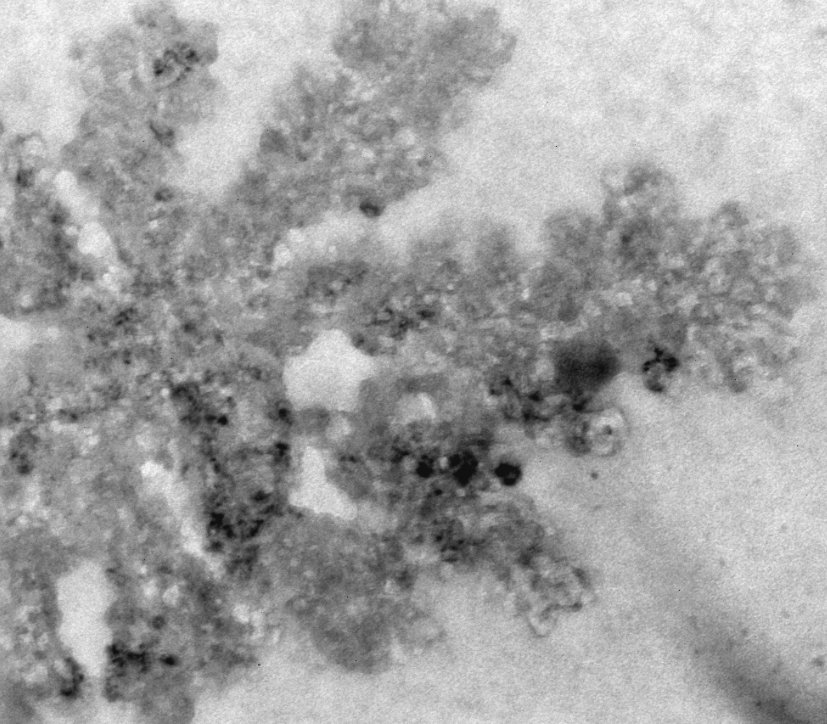
The next step was to produce VLPs with this new construct, which succeeded. The created biobricks are named [http://partsregistry.org/Part:BBa_K883160 BBa_K883160] & [http://partsregistry.org/Part:BBa_K883161 BBa_K883161]. VLPs were produced using BBa_K883161, which was at that moment present in the pSB1AK3 backbone in JM 109 cells. Protocols for growing the culture, dialysis of the VLPs and purifying the VLPs can be found here. Verification of VLP formation was done by Electron Microscopy (figure 11). In figure 12 a highly magnified image is shown of such a VLP with a negatively charged interior. As a proof of concept, the CCMV VLPs with a negatively charged interior were loaded with iron ions and monitored using electron microscopy. Unluckily, the samples were highly contaminated, which made it impossible to pinpoint any present VLPs. This contamination was possibly caused by the addition of iron to the samples. In figure 13 an image is shown of such a sample in which there is lots of contamination.
Hepatitis B with a K-coil on the inside
Deletions as well as modifications to the C-terminal of the Hepatitis B (HepB) core protein are possible since this part of the protein is not important for VLP formation [4]. Knowing this we can assume that the fusion of a K-coil to the C-terminal will lead to the formation of a VLP with a coil presented on the inside (figure 14).
To obtain the maximal amount of space in the VLP capsule we decided to delete a part of the C-terminal that is normally used for DNA binding and not required for VLP folding. After looking at protein folding predictions it was decided to add a short flexible linker between coil and core protein instead (see In silico folding prediction).
Methods
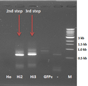
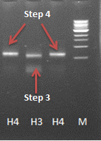
This modification was carried out in 4 PCR steps extending our construct one step at a time (see figures 15-17).
Results
After some problems with the last step of the PCR reaction a product with the correct length was obtained (see journal week 18). Unfortunately the ligation into a vector and transformation with E. coli did not succeed yet.
References
1. Minten, I.J., et al., Controlled encapsulation of multiple proteins in virus capsids. J Am Chem Soc, 2009. 131(49): p. 17771-3.
2. Arai, R., H. Ueda, et al. (2001). "Design of the linkers which effectively separate domains of a bifunctional fusion protein." Protein Eng 14(8): 529-532.
3. Douglas, T., et al., Protein Engineering of a Viral Cage for Constrained Nanomaterials Synthesis. Adv. Mater., 2002. 14, No. 6. March 18. p. 415-18.
4. Beterams, G., Böttcher B., & Nassal M. (15. Sept 2000). Packaging of up to 240 subunits of a 17 kDa nuclease into the interior of recombinant hepatitis B virus capsids. FEBS Lett., S. 169-76.
 "
"


