Team:Technion/Project/RS
From 2012.igem.org
(→The positive control) |
(→Additional cloning) |
||
| Line 41: | Line 41: | ||
==Additional cloning== | ==Additional cloning== | ||
| - | <p align="left">The generated RS+mCherry was planned to be used in YES gate #3 of our system. Therefore, it has been cloned downstream to the PLux promoter and submitted as [http://partsregistry.org/wiki/index.php?title=Part:BBa_K784013 BBa_K784013]. Moreover, a positive control has been generated using the method described above and submitted as [http://partsregistry.org/wiki/index.php?title=Part:BBa_K784014 BBa_K784014]. These BioBricks were planned to be assembled upstream to [http://partsregistry.org/Part:BBa_I0462 BBa_I0462] for characterization of induction by both [http://partsregistry.org/3OC6HSL 3OC<sub>6</sub>HSL] and theophylline.</p> | + | <p align="left">The generated RS+mCherry was planned to be used in YES gate #3 of our system. Therefore, it has been cloned downstream to the PLux promoter and submitted as [http://partsregistry.org/wiki/index.php?title=Part:BBa_K784013 BBa_K784013]. Moreover, a positive control has been generated using the method described above and submitted as [http://partsregistry.org/wiki/index.php?title=Part:BBa_K784014 BBa_K784014]. These clones were verfied via colony PCR and sequencing. These BioBricks were planned to be assembled upstream to [http://partsregistry.org/Part:BBa_I0462 BBa_I0462] for characterization of induction by both [http://partsregistry.org/3OC6HSL 3OC<sub>6</sub>HSL] and theophylline.</p> |
| + | |||
==Results== | ==Results== | ||
===MCS+tac+RS+mCherry=== | ===MCS+tac+RS+mCherry=== | ||
Revision as of 20:47, 25 September 2012

Contents |
What is a Riboswitch?
Riboswitches are regulatory elements and can control translation of genes. They consist of a short mRNA sequence that can fold to create a structure. This structure can be changed in the presence of a specific ligand. The regulatory function is achieved if the mRNA structural change can determine if a gene will be translated. In bacteria this can be done by placing the riboswitch before a RBS and ensuring that it will block the ribosome from the RBS, and that after the ligand is added the structural change will allow the ribosome access to the RBS. It is important to note that the function of the RS can be affected by the coding region downstream to it {1,2}.
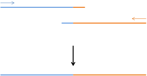
Fusion PCR
The technique is also known as [http://openwetware.org/wiki/Assembly_pcr assembly PCR]. This technique allows fusing together any two DNA pieces in a precise way, and without having to rely on restriction sites. This is accomplished by careful planning of primes so that for each DNA piece there are 2 primers: in the fused area the primer has a complementary area for the DNA piece and also a complementary area for the second DNA piece; normal primer for the non-fused end {3}.
The first step is to elongate each of the DNA pieces so that each will contain a complementary region for the other DNA piece. This is done by normal PCR {3}.
The second step is to elongate both DNA pieces in the same PCR reaction using only the outer primers. This way the overlapping region of the DNA pieces will act as a third primer, resulting in fused product that contains both DNA pieces {3}.
General design
We used a synthetic theophylline riboswitch, clone 12.1, that was created by S.A Lynch and J.P Gallivan{1}.
We chose to use this kind of regulatory element for the following reasons:
- In our project we are using several different regulatory elements and we need them to work together with little or none crosstalk. Most of the regulatory elements are inducible promoters. We had a hard time finding more inducible promoters that are well defined and don’t crosstalk with the rest of our promoters. So we looked for another kind of regulatory element.
- Riboswitches were discovered only in 2002, and the synthetic ones were created not long after.
- Riboswitches can be useful to future iGEM teams and the rest of the synthetic biology community as an additional and unique regulatory element.
In our project we use Riboswitches with a reporter gene (mCherry) and RNA polymerases: T7, T7*, SP6, T7*(T3),T7*( K1F), T7*(N4) (later notated as T3, K1F and N4){4}.
In order to combine the riboswitch with the different genes we use fusion PCR. We use it because in order for the riboswitch to work the start codon of the gene should be adjacent and downstream to the RBS. This is due to the start codon part in the specific riboswitch structure.
The cassettes that are used in the plasmids are shown in Figure 2.
The Riboswitch is very short (74 bp including the RBS) and it could be a problem with PCR, so we’ve extracted it with 430 bp upstream (part of the pUC19 plasmid) and the long Riboswitch is then 504 bp long. Moreover, the added part from pUC19 contains an MCS (which contains an EcoRI site) and a tac promoter. By adding a PstI site to the end of the RNAP polymerases or mCherry (by carefully planning the primer) we could clone the fusion product into pSB1C3.
The summary of our fusion PCR strategy is presented in Figure 3.
RS+mCherry characterization
Experimental setup
In order to provide quality information about the riboswitch function, we fused the MCS+tac promoter+RS construct from the pUC19 to the mCherry protein. The resulting construct was used in a plate reader assay to measure the level of fluorescence as a function of theophylline concentration. After consulting with Dennis Mishler from the Gallivan lab, we learned that full induction of translation should occur at 2mM of theophylline. Thus, we planned a dose response experiment with concentration ranging from 0-8mM theophylline. Several experiments were done, as described in the results section of this page.
During the second set of experiments, a negative and a positive control were introduced. The negative control is pSB1C3 with an MCS insert. The positive control is a plasmid in which the RS was deleted and replaced with a spacer region with the RBS from the riboswitch.
All plate reader experiments were done in E. coli TOP10 strain. Briefly, starters were grown over night, diluted 1:100, grown to ~O.D 0.6 and divided into 48 well plates. IPTG was added (to 1mM concentration) to induce the tac promoter and different concentrations of theophylline were added. Controls without IPTG and without theophylline were prepared as well. The samples were incubated at 37 degrees for ~3-4.5 hours before measuring fluorescence in the plate reader.
The positive control
The positive control was constructed by doing a PCR reaction to amplify a plasmid with MCS+tac+RS+mCherry without the RS part. The primers were designed with tails which created a spacer region and a PacI restriction site upstream to the RBS from the RS. The PCR products were digested with PacI and self ligated to produce the positive control plasmids. This process was done on several constructs in parallel in order to save time. Some of the constructs contained mutations in the spacer region which should be affecting the RBS strength. Thus, we disregard those differences in the spacer region when looking at our results.
Additional cloning
The generated RS+mCherry was planned to be used in YES gate #3 of our system. Therefore, it has been cloned downstream to the PLux promoter and submitted as [http://partsregistry.org/wiki/index.php?title=Part:BBa_K784013 BBa_K784013]. Moreover, a positive control has been generated using the method described above and submitted as [http://partsregistry.org/wiki/index.php?title=Part:BBa_K784014 BBa_K784014]. These clones were verfied via colony PCR and sequencing. These BioBricks were planned to be assembled upstream to [http://partsregistry.org/Part:BBa_I0462 BBa_I0462] for characterization of induction by both [http://partsregistry.org/3OC6HSL 3OC6HSL] and theophylline.
Results
MCS+tac+RS+mCherry
First experiment
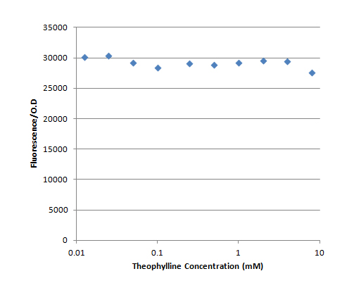
The first set of experiments was done in pSB1C3, which is a high copy plasmid backbone. This set of experiments lacked a negative and a positive control. The fluorescence divided by the O.D. as a function of the theophylline concentration is presented in Figure 4. Each result is an average of a duplicate.
It can be seen that there was no increase in the fluorescence when the theophylline concentration was increased, in contrast to our expectations. Moreover, the fluorescence/O.D value of the no IPTG control was ~32000.
The intermediate conclusion at this stage was that the mCherry might be accumulating in the cell due to the high copy number of the plasmid. Since the TOP10 strain has only low level of lacI, the transcription from the tac promoter occurs continuously. Therefore, the basal translation level is enough for the mCherry to accumulate.
Second set of experiments
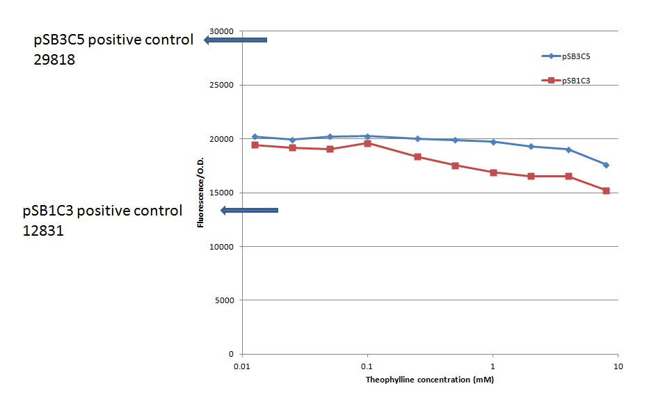
The second set of experiments was done in pSB3C5, which was believed to be a low copy plasmid backbone, in addition to repeating the experiment in pSB1C3. This set of experiments did have a negative and a positive control, as described above. The fluorescence divided by the O.D. as a function of the theophylline concentration is presented in Figure 5. Each result is an average of a duplicate. The negative control has been deducted from all the results.
It can be seen that there was no increase in the fluorescence when the theophylline concentration was increased, in contrast to our expectations. Again, the no IPTG control gave similar results to 0mM theophylline. The positive control in pSB3C5 gives ~1.5 higher result than the RS results, as expected. However, the positive control in pSB1C3 gives ~1.5 lower result than the RS results. It should be noted that there is a slight difference in the sequence of the positive controls in the spacer region, due to mutations during the cloning process.
While working with the pSB3C5 backbone we noticed that it gave higher miniprep results than pSB1C3 which made us suspect that it is not low copy. Therefore, we decided to repeat the experiment in a verified low copy backbone from Roee, which was notated pCP.
Third set of experimetns
This final set of measurements was done in pCP. The inserts were taken from the pSB3C5 backbone from the previous experiment. This set of experiments did have a negative and a positive control, as described above. The fluorescence divided by the O.D. as a function of the theophylline concentration is presented in Figure 6. Each result is an average of a duplicate. The negative control has been deducted from all the results.
It can be seen that there was no increase in the fluorescence when the theophylline concentration was increased, in contrast to our expectations. Again, the no IPTG control gave similar results to 0mM theophylline. The positive control gave ~3 times lower results than the RS results.
Conclusions
Considering all the results above, several observations can be made. Firstly, the riboswitch does not respond to changes in theophylline concentration. Secondly, high levels of fluorescence indicate that translation occurs in the absence of theophylline. Thirdly, the positive control seems to malfunction, giving lower results than the riboswitch (except for the experiment in pSB3C5). On the other hand, there might be some effect of the surrounding sequences on the RBS strength. Finally, the plasmid copy number did not have a significant effect on the results.
Taking all of the above observations into account, we believe that the main reason for the riboswitch failure is due to an effect of the coding region of mCherry on the riboswitch function. A modeling effort has been made to support this assumption using [http://www.nupack.org/ NUPACK] secondary structure prediction and the Salis lab RBS calculator. Check out the documentation on our modeling page.
Future directions
There are several future directions we could pursue:
- To make sure that our experimental setup is correct, we could repeat the experiment done by Lynch and Gallivan {1} with the riboswitch fused to IS10+lacZ (IS10 is a coding region upstream to lacZ).
- If the experimental setup is good, we can attempt fusing the RS to a variety of different fluorescent proteins. Moreover, we could fuse the fluorescent proteins to the IS10 coding region instead of to the RS. This way the mRNA in close proximity downstream to the riboswitch will be identical to a system that has already been shown to work.
- We could fuse the RS to fluorescent proteins with degradation tags, thus eliminating the possibility of accumulation of the fluorescent protein.
- We could repeat the experiment in an E. coli strain with high levels of lacI, thus ensuring that there is no transcription before the induction of the system.
RS with polymerases
We have been trying to fuse the Riboswitch with different RNA polymerases (2775bp). We started with the polymerases: T7, T7* (different from T7), T3, N4, K1F, SP6. After a lot of work on SP6 Inbal found out that we have not been working with the SP6, so we’ve dropped it from a lack of time.
After several failed fusion PCR attempts we figured out that the right Tm was 55-56°C for all but K1F whose Tm was 55-57°C. The fused product was 3293 bp, as you can see in Figure 7.
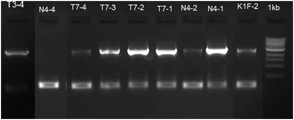

After this step we cut the part pUC19+riboswitch+polymerase with EcoRI and PstI restriction enzymes and it removed most of pUC19 remains, resulting in a 2919 bp insert. This has been done for inserting the insert to the pSB1C3 plasmid for easier next PCR step. The resulting gel is presented in Figure 8.
The last step was to prepare the fused Riboswitch with the different polymerases for BioBrick standard. So we needed to remove any unnecessary DNA upstream to the Riboswitch and add the necessary BioBrick prefix and suffix. We chose to do it by PCR with a sense primer that is complementary to the start of the Riboswitch and have an overhang of the prefix and an anti-sense primer with a suffix overhang. We got the correct band length on an agarose gel, which is presented in Figure 9.
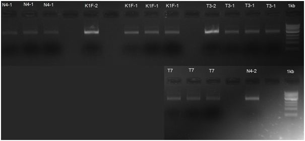
After the transformation we did a colony PCR to verify if the clones got the insert, but only got results for 4 clones that contain Riboswitch with N4 polymerase and one with Riboswitch with T7 polymerase. The colony PCR results are presented in Figure 10.
References
- Lynch S. A., Gallivan J. P. 2009. A flow cytometry-based screen for synthetic riboswitches. Nucleic Acids Research 37(1): 184-192.
- Suess B., et al. 2004. A theophylline responsive riboswitch based on helix slipping controls gene expression in vivo. Nucleic Acids Research 32(4): 1610-1614.
- Yon J., Fried M. 1989. Precise gene fusion by PCR. Nucleic Acids Research 17(12).
- Temme K., et al. 2012. Modular control of multiple pathways using engineered orthogonal T7 polymerases. Nucleic Acids Research (advance access): 1-9.
 "
"


