Team:TU-Delft/Modeling/Diffusion
From 2012.igem.org
(→Final Device Model - The Snifferometer) |
(→Final Device Model - The Snifferometer) |
||
| Line 91: | Line 91: | ||
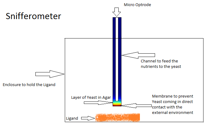
Different models were analyzed for their suitability before arriving at the final design in Figure 4. The device at the bottom has a membrance preventing the yeast coming in direct contact with external substances, above which is a layer of agar in which yeast is placed, the nutrients for it's growth is fed in through a channel along the sides of the tube using which the yeast cells can also be replaced as and when needed. A micro-optrode is then used to sense the photons emitted by the fluoroscent proteins. | Different models were analyzed for their suitability before arriving at the final design in Figure 4. The device at the bottom has a membrance preventing the yeast coming in direct contact with external substances, above which is a layer of agar in which yeast is placed, the nutrients for it's growth is fed in through a channel along the sides of the tube using which the yeast cells can also be replaced as and when needed. A micro-optrode is then used to sense the photons emitted by the fluoroscent proteins. | ||
| - | |||
| - | |||
| - | |||
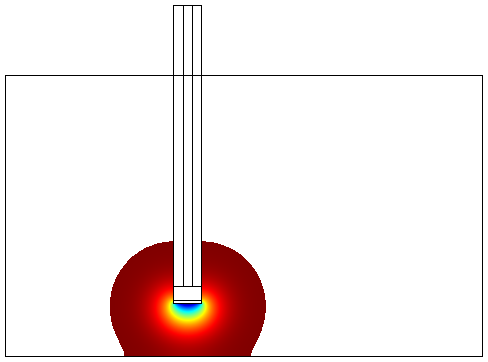
The values for various dimensions of the model were chosen using an iterative approach of design and analysis which would yield an optimal response. The model dimensions can be obtained from the code in the codes section. Once the structure of the device was designed, a simple reaction model assuming linear kinetics was implemented in the agar layer using the results of the single cell pathway model([https://2012.igem.org/Team:TU-Delft/Modeling/SingleCellModel#Results '''Results'''])[[File:NoConvection.png|300px|left|thumb|'''Figure 5''': Device Modeled without convection]] | The values for various dimensions of the model were chosen using an iterative approach of design and analysis which would yield an optimal response. The model dimensions can be obtained from the code in the codes section. Once the structure of the device was designed, a simple reaction model assuming linear kinetics was implemented in the agar layer using the results of the single cell pathway model([https://2012.igem.org/Team:TU-Delft/Modeling/SingleCellModel#Results '''Results'''])[[File:NoConvection.png|300px|left|thumb|'''Figure 5''': Device Modeled without convection]] | ||
Revision as of 22:51, 23 October 2012


One of the main objectives of the project was to synthesize a practical device, the Snifferometer for tuberculosis detection. As a first step towards achieving this goal, we built a temporal model of the system using PDE's which was simulated in matlab. A spatio temporal 2D reaction-diffusion system was then implemented in COMSOL multiphysics using the knowledge obtained from single cell pathway model, combining the behaviours of the which helped us get a better understanding of how such a device could be implemented and the response times involved in such a process.
Contents |
Initial model of the device
Setup of the model
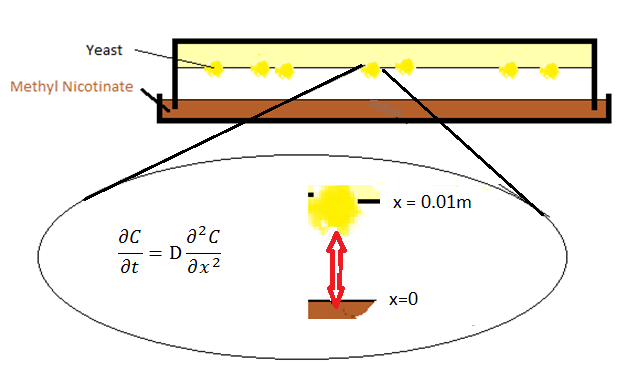
The initial setup of the device consisted of two parts: a petridish with the ligand which forms the bottom layer and agar with the olfactory yeast which forms the top layer. The ligand molecules diffuse through air from the petridish into the agar.
Modeling Approach
PDEs
The diffusion phenomenon is modelled by Fick's second law.

where C represents the ratio of the pressure between gasphase and atmosphere, x is the distance from the surface of petridish to the agar layer, and D is the diffusion coefficient, the value of which is calculated from [1].
In order to solve PDEs, numerical methods are used as approximation.
On the left side of the equation, the Euler forward method is taken:

On the right side of the equation, the central differential method is used:

It can be noticed that the equations both to the right and left of the equality are the same.

Therefore, the PDEs can be numerically replaced by the equation:

where 
Boundary conditions
In order to solve this equation, boundary conditions are required. Two boundary conditions are set for these two surfaces of petridish-air and air-agar.
- At x=0, the Dirichlet boundary condition was placed:

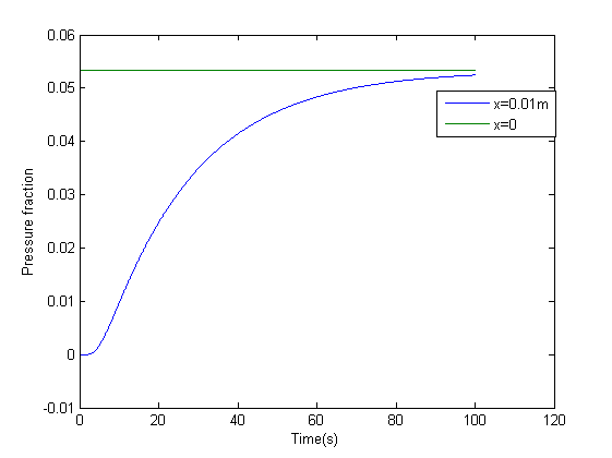
with Csat being the pressure ratio with respect to the saturation pressure of the specific compound being IsoAmylAcetate as an example in our model. For IsoAmylAcetate this value is 533.3 Pa at room temperature. Thus Csat is equal to 0.05333.
- One can take Neumann boundary condition at x=l, where l is the distant between petridish and agar and assumed to be 0.01 meter in the model. The reason we can use Neumann boundary is because the molecules bounce back into the gasphase against the agar surface.

The model was the simulated in matlab, the results of which are below
Figures 2 and 3 depict the results of the simulation with distance dimension 0 - 0.01 meter and the time dimension 0 - 100 seconds.
- Matlab script for diffusion model can be found here.
conclusion
Two key observations were drawn from this model
- The results suggest that at approximately two minutes, there is steady state concentration at the agar layer
- The input to the single cell pathway model can be considered a step function, if we assume that the Ligand is not degraded by yeast.
Final Device Model - The Snifferometer
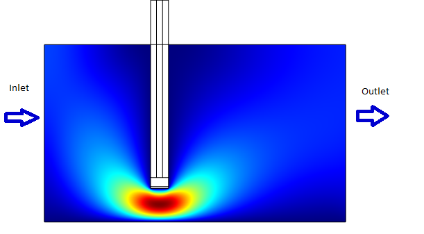
One of the other goals of the diffusion modeling was to model the device which we intended to build for the project. We made use of the finite element analysis simulator Comsol Multiphysics[3]
for developing this model.Different models were analyzed for their suitability before arriving at the final design in Figure 4. The device at the bottom has a membrance preventing the yeast coming in direct contact with external substances, above which is a layer of agar in which yeast is placed, the nutrients for it's growth is fed in through a channel along the sides of the tube using which the yeast cells can also be replaced as and when needed. A micro-optrode is then used to sense the photons emitted by the fluoroscent proteins.
The values for various dimensions of the model were chosen using an iterative approach of design and analysis which would yield an optimal response. The model dimensions can be obtained from the code in the codes section. Once the structure of the device was designed, a simple reaction model assuming linear kinetics was implemented in the agar layer using the results of the single cell pathway model(Results)
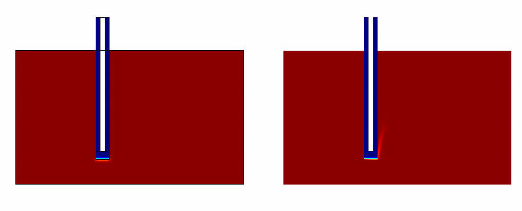
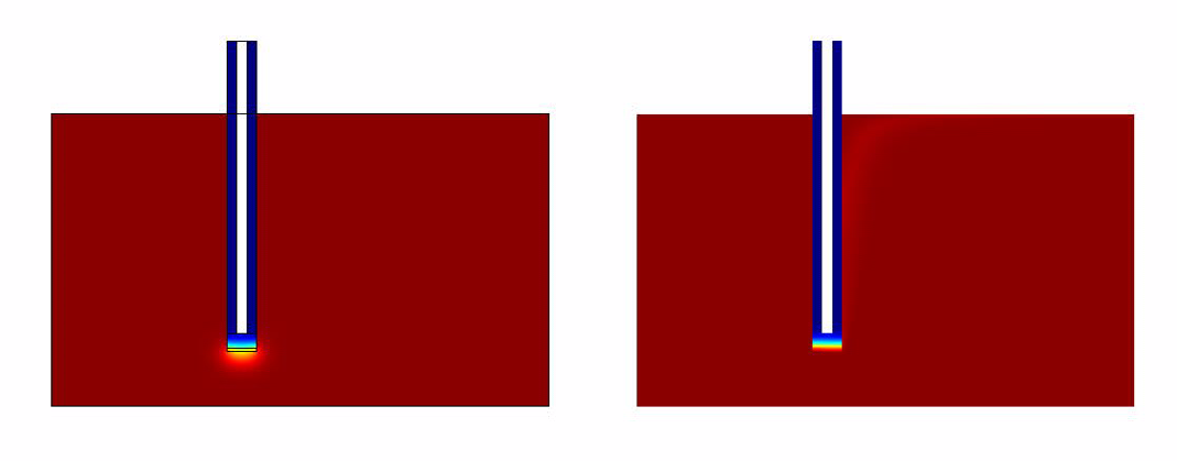
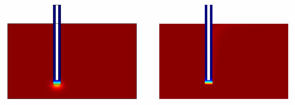
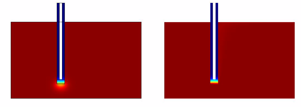
- Without Convection (which simulates the case of a stationary ligand like a sample of saliva).
- With Convection (which simulates a continuous flow of Ligand for eg: A spirometer)
Simulation Results
The results of the simulation over 45 mins duration is shown in the figures below. Please click on the link for the complete simulation.File:DiffusionModelSimulation.swf

|
|
|
|
|
Conclusion
From the simulations and analysis that were done, the following things could be concluded
- The convection model responds much faster when compared to the convectionless model.
- It takes around 40 mins for the system to generate quantifiable output.
- The rate limiting factor was found not to be the diffusion but the GFP production from the pathway.
Limitations
The time scale of the project did not allow us to conduct experiments to validate the findings of the model.
Future Work
As the model is in it's initial stages of conception, it leaves room open for further research into the characteristics of the device. Some of the points we are looking at working in the future are
- Conduct experiments to validate the results of the model.
- Re-estimating the parameters if needed.
- Building the actual device
 "
"

